Under-hood engine air intake system

a technology for air intake systems and under-hood engines, which is applied in the direction of machines/engines, combustion-air/fuel-air treatment, transportation and packaging, etc., can solve the problems of only intensifying disadvantages, obstructing visibility for work vehicle operators, and it is not possible to adapt conventional above-hood pre-cleaners to under-hood air intake designs without extensive modifications. , to achieve the effect of reducing or minimizing the intake of preheated air

Inactive Publication Date: 2005-09-29
DEERE & CO
View PDF15 Cites 54 Cited by
  • Summary
  • Abstract
  • Description
  • Claims
  • Application Information

AI Technical Summary

Benefits of technology

[0004] Conventional above-hood air intake systems for work vehicles obstruct visibility for the work vehicle operator. This is a consequence of attempting to meet the noted demands of locating the air intake (1) high enough to eliminate the entry of dus

Problems solved by technology

Conventional above-hood air intake systems for work vehicles obstruct visibility for the work vehicle operator.
These disadvantages are only intensified by the pre-cleaners that are often attached to these systems in high debris environments.
A major disadvantage of conventional under-hood air intake systems wh

Method used


Image

  • Under-hood engine air intake system
  • Under-hood engine air intake system
  • Under-hood engine air intake system

Examples


Embodiment Construction

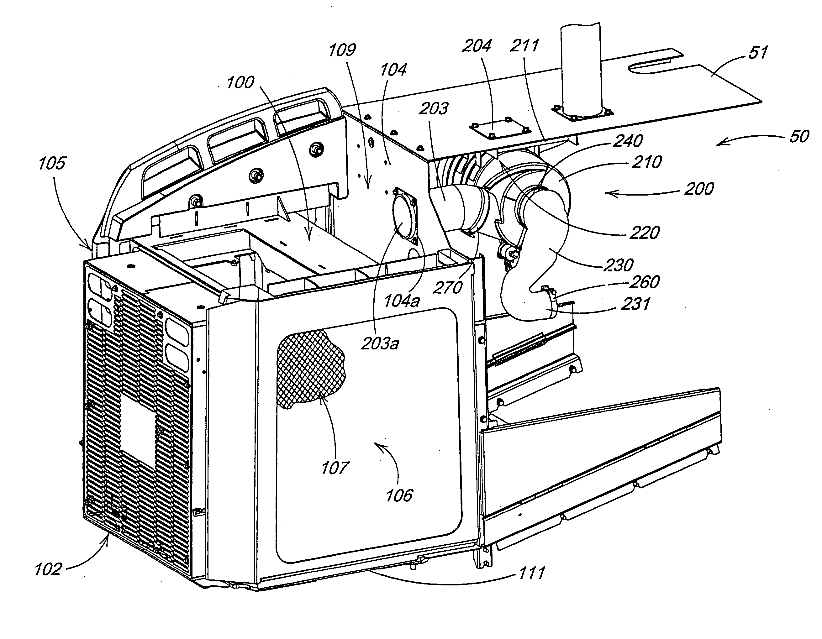
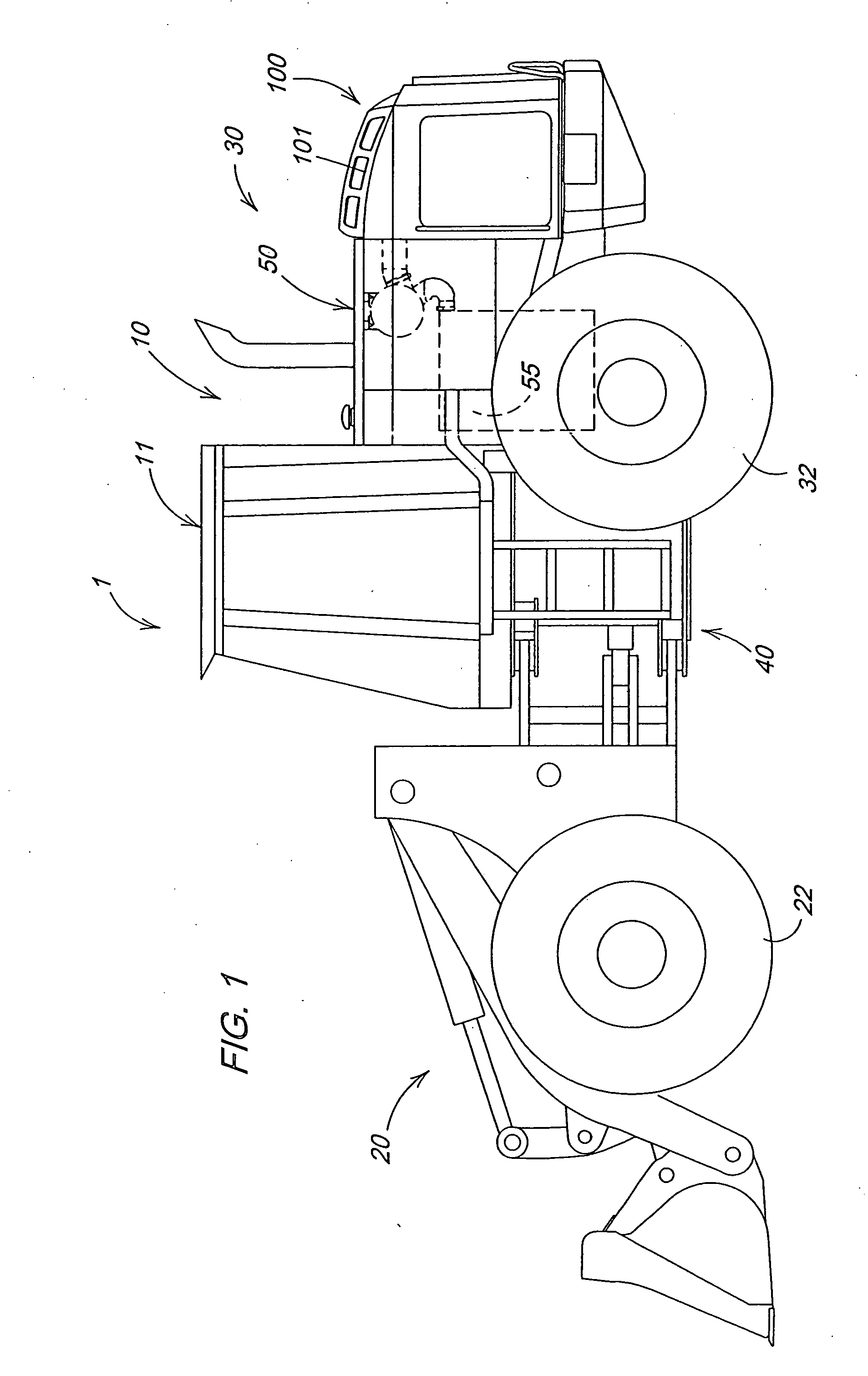
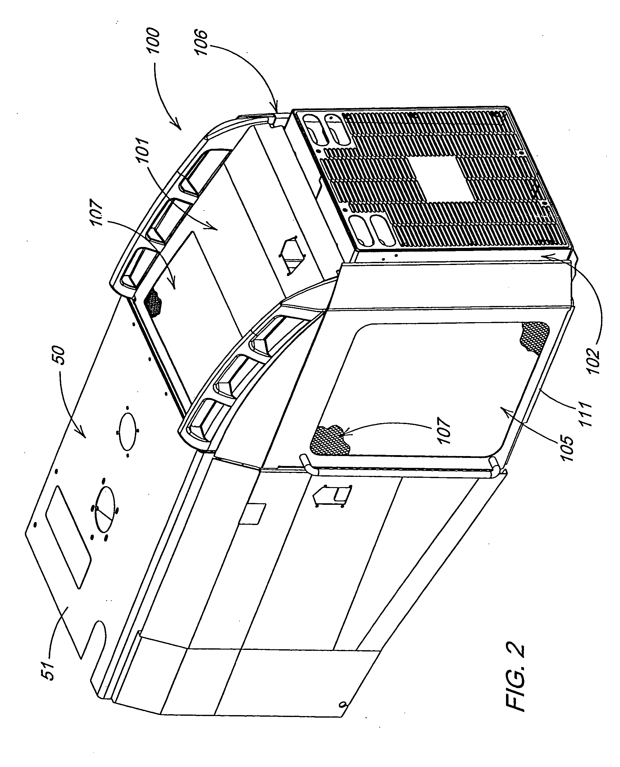
[0013]FIG. 1 illustrates a work vehicle in which the invention may be used. The particular work vehicle illustrated in FIG. 1 is an articulated four wheel drive loader 1 having a body 10 that includes a front body portion 20 pivotally connected to a rear body portion 30 by vertical pivots 40, the loader being steered by pivoting of the front body portion 20 relative to the rear body portion 30 in a manner well known in the art. The rear body portion 30 includes an engine compartment 50 and a separately accessible plenum cooling compartment 100. The front and rear body portions 20 and 30 are respectively supported on front drive wheels 22 and rear drive wheels 32. An operator's station 11 is provided on the rear body portion 30 and is generally located above the vertical pivots 40. The front and rear drive wheels 22 and 32 propel the vehicle along the ground and are powered in a manner well known in the art. FIG. 2 shows a detailed oblique view of the rear body portion 20 illustrated...


PUM


Abstract

An engine air intake system including an engine air intake device and a plenum cooling compartment that is separate from the engine compartment by a baffle. The plenum cooling compartment is formed by the baffle, side doors, a fan door and a floor and contains a heat exchanger. A fan draws outside ambient air into the plenum cooling compartment, via perforations in the top and side doors, and out of the plenum cooling area via the heat exchanger. The cooling compartment is designed such that a distance between the heat exchanger and the baffle provides a gap from which the engine air intake device removes ambient air as a source for engine air. An option is provide for the system to withdraw outside ambient air from an area external to the plenum cooling compartment in high debris environments. The engine air intake system cleans the air before supplying it to the engine.

Description

FIELD OF THE INVENTION [0001] The invention relates to the structure and operation of air intake systems and to methods of supplying intake air to internal combustion engines. More specifically, it relates to a method, system and apparatus for supplying ambient or non-preheated air to an internal combustion engine for a work vehicle such as, for example, a mobile construction machine. BACKGROUND OF THE INVENTION [0002] Most mobile construction machines have an above-hood air intake. The above-hood air intake is usually covered by a shield to prevent the entrance of rain and other precipitation. Above-hood air intakes are typically designed to be low profile, i.e., evince a small signature. However, these intakes are required to be high enough to minimize the entry of dust and other debris settling near the hood and far enough from the exhaust stack associated with these machines to minimize the intake of preheated air. Pre-cleaners are typically available for above-hood air intake d...

Claims


Application Information

Patent Timeline
IPC IPC(8): B60K11/00B60K11/04B60K11/08B60K13/02F01P1/00F01P11/12F02M35/04F02M35/16
CPCB60K11/04B60K13/02B60Y2200/41E02F9/0866E02F9/0891Y02T10/144F01P2001/005F02M35/04F02M35/10157F02M35/164F01P11/12Y02T10/12B60K11/08
Inventor PFOHL, JESSE LEEMAIFIELD, CHRISTOPHER JAMESMEYER, DOUGLAS GERARDHUEGERICH, DANIEL JOSEPHWERNER, GREGORY KEITH
Owner DEERE & CO
Why Eureka
Try Eureka