
Refiner sensor and coupling arrangement

a technology of which is applied in the field of refiner sensor and coupling arrangement there, can solve the problems of difficult to accurately measure parameters in the refining zone, such as temperature and pressure, and the quality of the resultant fiber product ultimately produced may not meet quality control standards, so as to improve the reliability and robustness of the sensor assembly and prevent the effect of sensor assembly failur

Inactive Publication Date: 2005-09-29
J & L FIBER SERVICES
View PDF99 Cites 12 Cited by
  • Summary
  • Abstract
  • Description
  • Claims
  • Application Information

AI Technical Summary

Benefits of technology

[0012] The invention is directed to a sensor assembly and arrangement for steam-tightly conveying the sensor assembly wiring to a location of the refiner where signals transmitted by the wiring can be processed or further conveyed to a location where the signals can be processed. As a result, sensor assembly reliability and robustness is improved and sensor assembly failure is prevented by steam-tightly shielding the sensor assembly and its wiring from stock and steam in the refining zone of the refiner in which the arrangement is disposed.
[0015] The sensor wiring is threaded out a fixture attached to the manifold and through a flexible reinforced hose until the wiring is received in a sensor connector. The manifold is mounted to the backside of the sensor refiner disk segment. The flexible reinforced hose preferably has a braided exterior that preferably is made of stainless steel or another tough and durable material. The hose preferably includes a liner in which the sensor wiring is disposed that helps shield the wiring from the harsh environment within the refiner.
[0017] The puck is mounted so as to position the electrical connector generally in line with the instrument ports such that a conduit arrangement can sealingly engage the puck. The conduit arrangement includes a section of outer conduit that is received in the instrument ports and which engages the puck. The conduit arrangement also includes a tube received in the outer conduit that carries a male electrical connector that mates with the female electrical connector when the conduit arrangement is inserted into the instrument ports and engaged with the puck. Preferably there is a seal disposed between the tube and outer conduit that prevents steam from passing therebetween.
[0018] The outer conduit preferably threadably engages the puck and a portion of the instrument port that is located adjacent the puck. The tube is held captive within the conduit with its electrical connector coupled with the electrical connector of the puck. An anchor nut that is threadably received adjacent the opposite end of the conduit bears against a shoulder of the tube to help keep the tube captive within the conduit such that its connector remains coupled with the connector of the puck when the conduit is threadably engaged with either the instrument port, the puck connector body, or both. The free end of the tube preferably is sealed by a cap that retains a sealing plug through which sensor wiring passes to the exterior of the conduit arrangement.
[0019] Objects, features, and advantages of the present invention include a sensor that is capable of sensing a parameter or characteristic of conditions in the refining zone; that is robust as it is capable of withstanding severe vibration, heat, pressure and chemicals; is capable of repeatable, accurate absolute measurement of the refining zone characteristic or parameter; is simple, flexible, reliable, and long lasting, and which is of economical manufacture and is easy to assemble, install, and use.
[0020] Other objects, features, and advantages of the present invention includes a conduit arrangement that enables sensor wiring to be routed to the exterior of the refiner while preventing steam from escaping from the refining zone; a conduit arrangement that is steam tight; is formed using a minimum of machining steps, time and components; can be devised for any rotary disk refiner; is capable of being used in a refiner without modification of the refiner; and is simple, flexible, reliable, and robust, and which is of economical manufacture and is easy to assemble, install, and use.

Problems solved by technology

However, this has always been a problem because the conditions in the refining zone are rather extreme making it rather difficult to accurately measure parameters in the refining zone, such as temperature and pressure.
This often lead to an operator of the refiner or an automatic refiner control system making a change to a refiner control parameter, such as refiner gap, dilution water flow rate, chip mass flow rate, refiner disc pressure or force, or refiner disc best because it may not have been truly based upon actual conditions in the refiner zone.
Often, this takes a great deal of time, typically hours, for it to be determined whether the change made by the operator of the automatic refiner control system had the desire effect.
If it did not, it is possible that the quality of the resultant fiber product ultimately produced may not meet quality control standards.
This can cause paper made with the fiber to fail to meet quality control criteria for strength or some other parameter.
While this sensor assembly is capable of outputting a temperature measurement, the measurement outputted may not accurately reflect the temperature of stock in the refining zone.
As a result, temperature response is quite slow and not indicative of the actual temperature of stock in the refining zone.
Such sensor arrangements have been used in the past, but have not been satisfactory because of the effects of thermal inertia caused by the surrounding mass of the refiner disc.
Refiner control systems that receive temperature data from such sensors, are not as effective in controlling refiner operation because of this inherent time lag.
Due in part to this, the performance of these control systems has been less than optimal, leaving a great deal of room for improvement.
The reliability and robustness of sensor assemblies has also been an issue because of the rather harsh conditions to which they are exposed in the refining zone.
They are subjected to vibration, shock, temperature fluctuations, and pressure fluctuations that all can occur during refiner operation.
Any one of these things can cause sensor failure or a significant degradation in sensor performance.
Where a sensor is part of an array or group of sensors mounted to a refiner disc or in between refiner discs, the loss or degradation in performance of just a single sensor can have a significant impact.
One known problem that exists for temperature sensors is that the sensing element holder can loosen over time and get pushed axially into the refining disc in which it is disposed.
When this happens, the steam tight seal between the sensor assembly and the refiner disc can be compromised thereby causing steam and stock to leak from the refining zone through the bore in the refining surface completely through the disc.
Such a leak can lower the pressure in the refining zone, which can reduce refining efficiency, quality, and throughput.
Worse yet, stock and steam leaking from damaged sensor as well as other sensors that have not been damaged.
This ultimately can lead to failure of the entire array or group of sensors, effectively rendering the refiner control system inoperative.
When such down time is unplanned, it is particularly costly.

Method used


Image

  • Refiner sensor and coupling arrangement
  • Refiner sensor and coupling arrangement
  • Refiner sensor and coupling arrangement

Examples


Embodiment Construction

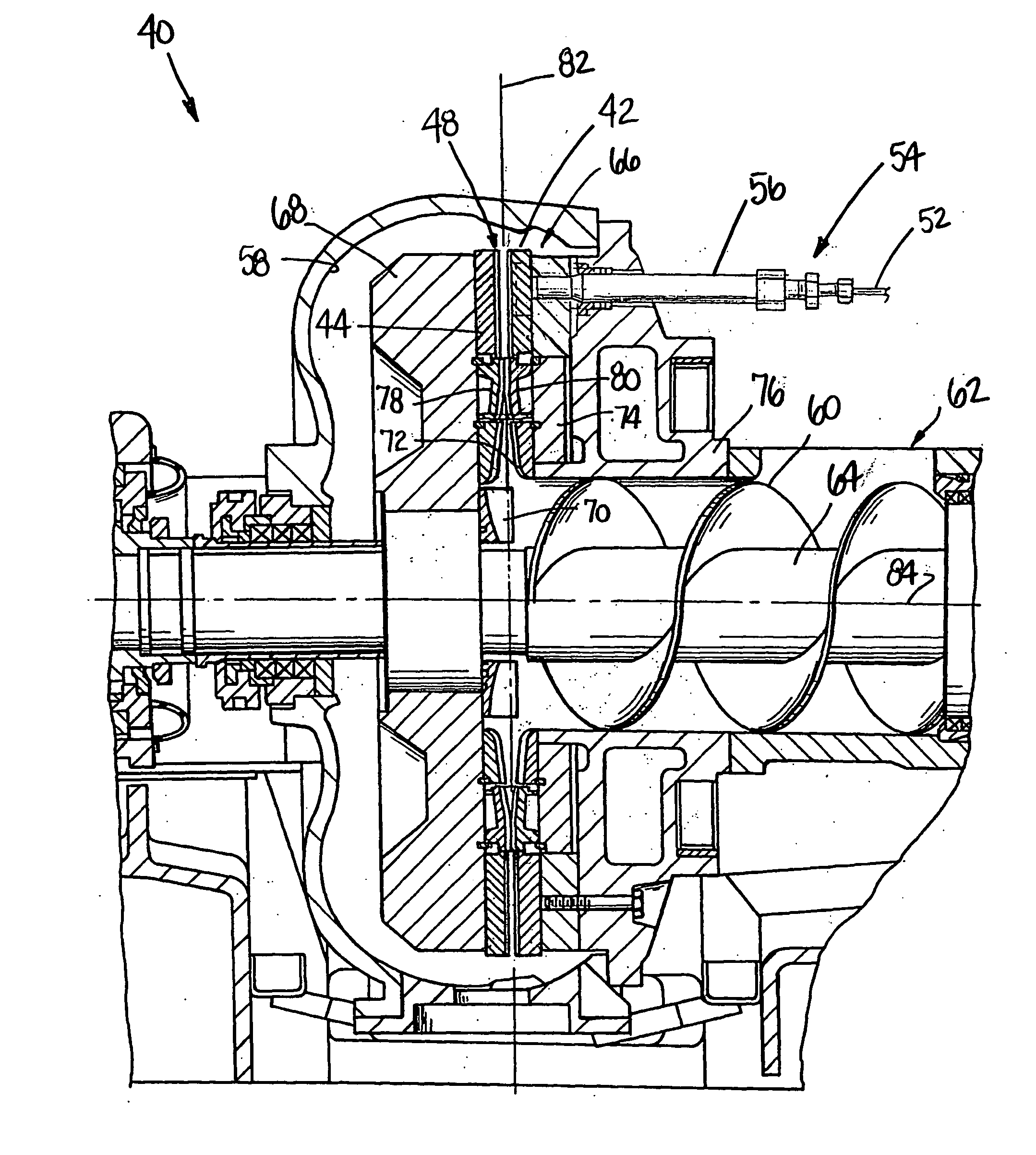
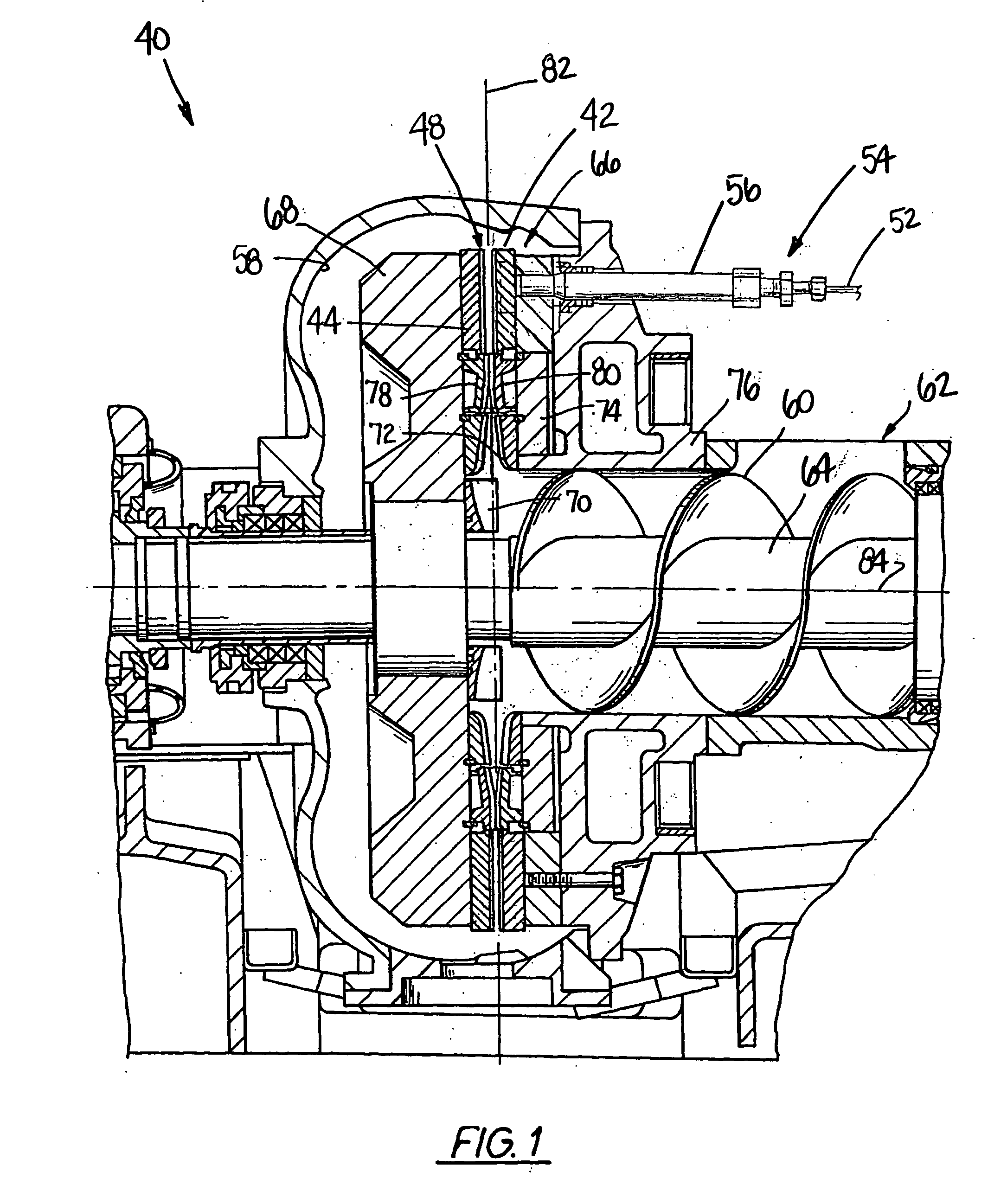
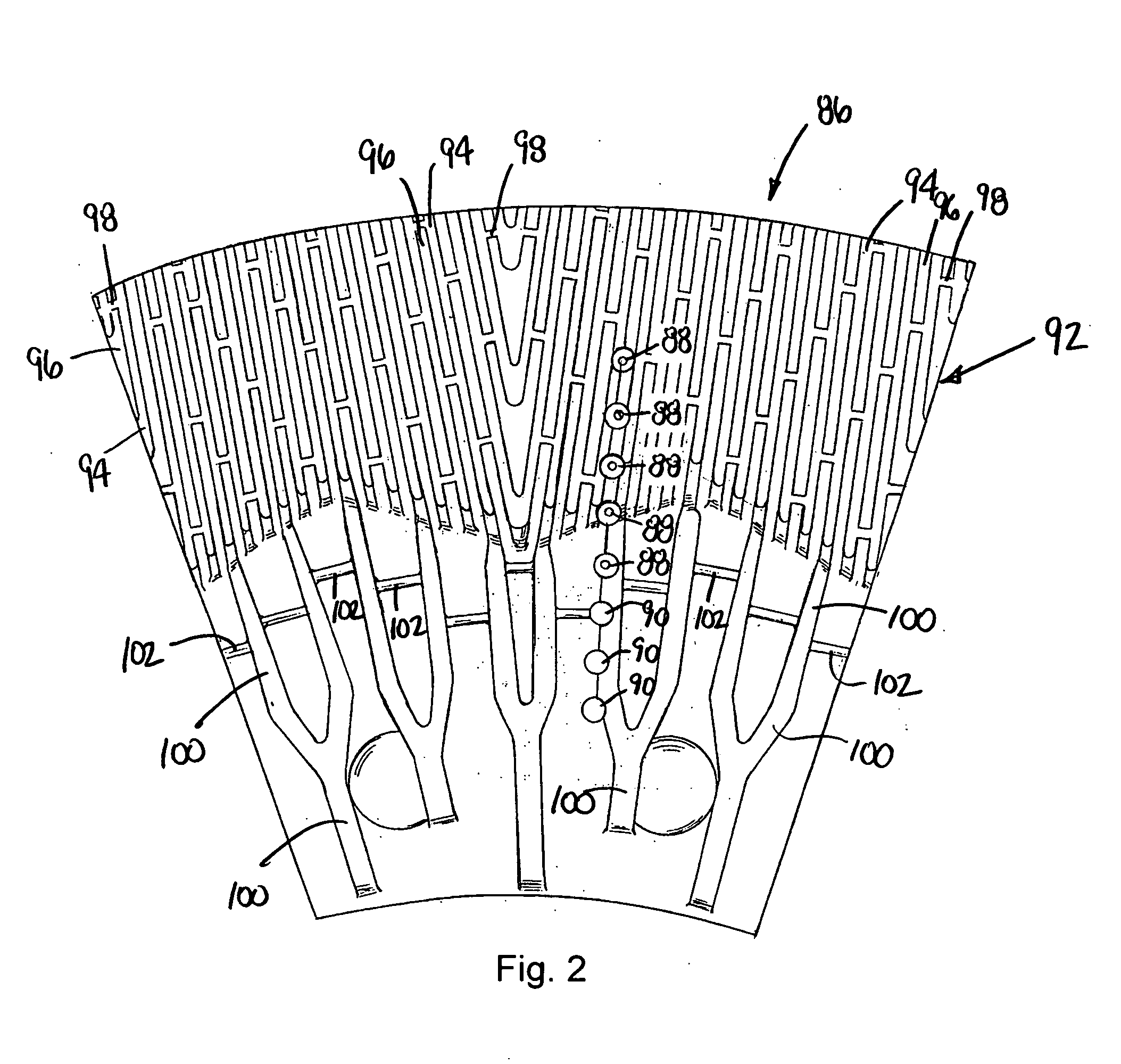
[0033]FIGS. 1-3 illustrate a refiner 40 that has a plurality of opposed refiner disks 42, 44, one of which carries a sensor arrangement 46 (FIG. 3) that is used to sense a parameter in a refining zone 48 located between the disks during refiner operation. The sensor arrangement 46 includes a plurality of sensor assemblies 50, each of which has a portion exposed to the refining zone 48 such that it contacts stock in the refining zone 48 during refiner operation. Sensor wiring 52 is received in a steam-tight conduit arrangement 54 that includes a section of conduit 56 that extends through a pre-existing instrument port in the refiner 40.

[0034] The refiner 40 has a housing or casing 58 and an auger 60 mounted therein which urges stock, typically in the form of a slurry of liquid and fiber, introduced through a stock inlet 62 into the refiner. The auger 60 is carried by a shaft 64 that is rotated during refiner operation to help supply stock to an arrangement of treating structure 66 w...


PUM


Abstract

A sensor assembly and coupling arrangement for a rotary disk refiner. The sensor assembly includes a housing formed by a base and frustoconical cap that has a sensing element carrying bulb extending outwardly therefrom. The coupling arrangement includes a conduit arrangement that is received in one or more aligned preexisting instrument ports of the refiner and that releasably couples with a connector puck. The puck is carried by the backside of a refiner disk segment that lies next to the refiner disk segment that is equipped with one or more sensor assemblies. Preferably, a flexible hose communicates sensor wiring from a sensor manifold that holds a plurality of sensor assemblies to the connector puck. The sensor manifold preferably is carried by the backside of the sensor refiner disk.

Description

FIELD OF THE INVENTION [0001] The present invention relates to a sensor assembly and coupling arrangement therefor for use in pulp processing equipment and more particularly to a sensor assembly and coupling arrangement therefor for a pulp processing refiner. BACKGROUND OF THE INVENTION [0002] Many products we use everyday are made from fibers. Examples of just a few of these products include paper, personal hygiene products, diapers, plates, containers, and packaging. Making products from wood fiber, fabric fiber and the like, involves breaking solid matter into fibrous matter. This also involves processing the fibrous matter into individual fibers that become fibrillated or frayed so they more tightly mesh with each other to form a finished fiber product that is desirably strong, tough, and resilient. [0003] In fiber product manufacturing, refiners are devices used to process the fibrous matter, such as wood chips, fabric, and other types of pulp, into fibers and to further fibril...

Claims


Application Information

Patent Timeline
IPC IPC(8): B02C7/11D21D1/00D21D1/30
CPCB02C7/11D21D1/30D21D1/002
Inventor LUTZ, MARK S.
Owner J & L FIBER SERVICES
Learn More