Line light source device and image information read-out apparatus

Inactive Publication Date: 2005-09-29
FUJIFILM HLDG CORP +1
View PDF9 Cites 4 Cited by
  • Summary
  • Abstract
  • Description
  • Claims
  • Application Information

AI Technical Summary

Benefits of technology

[0008] The primary object of the present invention is to provide a line light irradiating method, wherein an EL layer is utilized and wherein problems are capable of being preven

Problems solved by technology

However, with the line light source utilizing the EL layer described above, the problems with regard to EL characteristics are encountered in that, as the cumulative period of actuation of t

Method used


Image

  • Line light source device and image information read-out apparatus
  • Line light source device and image information read-out apparatus
  • Line light source device and image information read-out apparatus

Examples


first embodiment

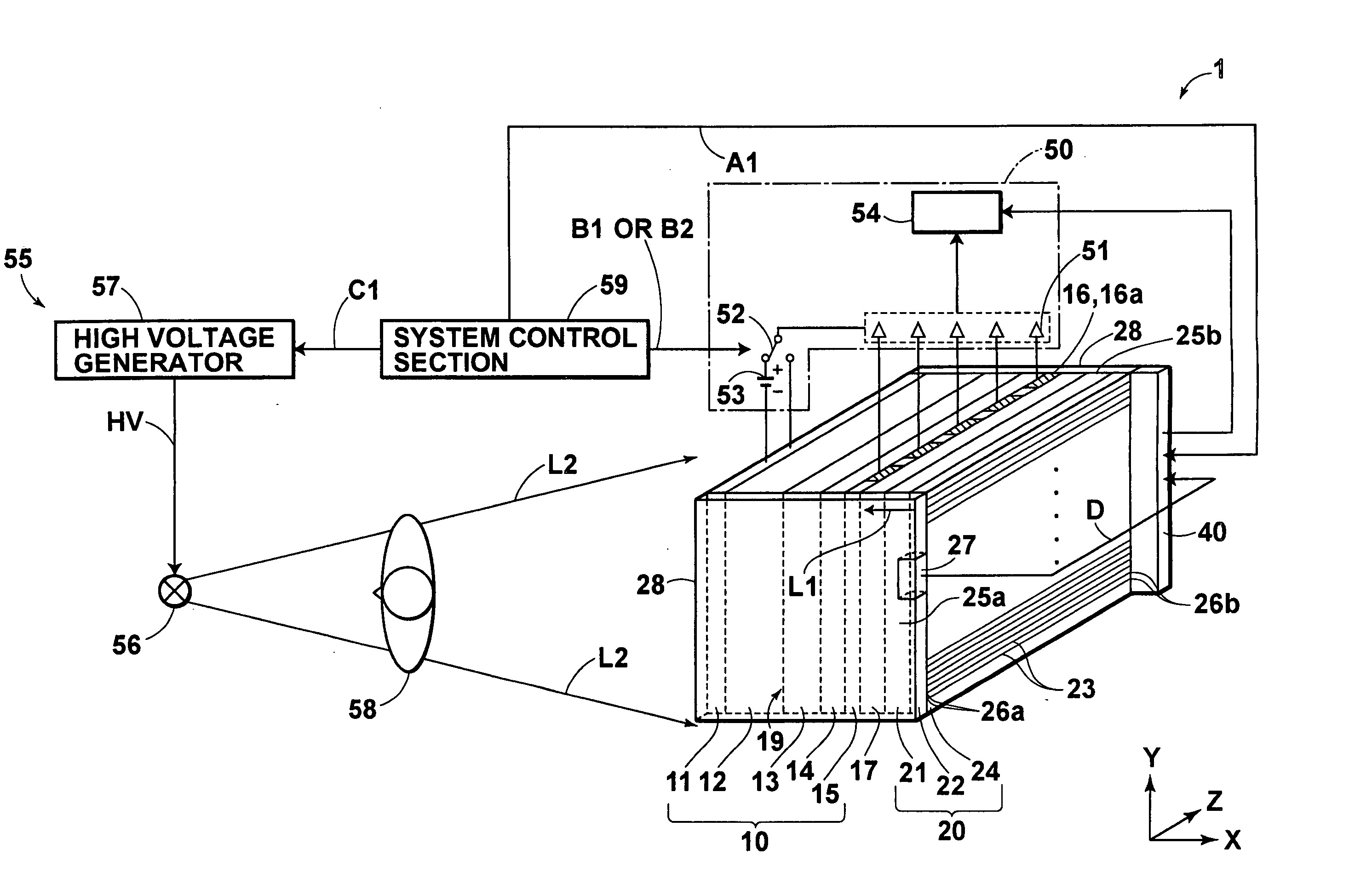
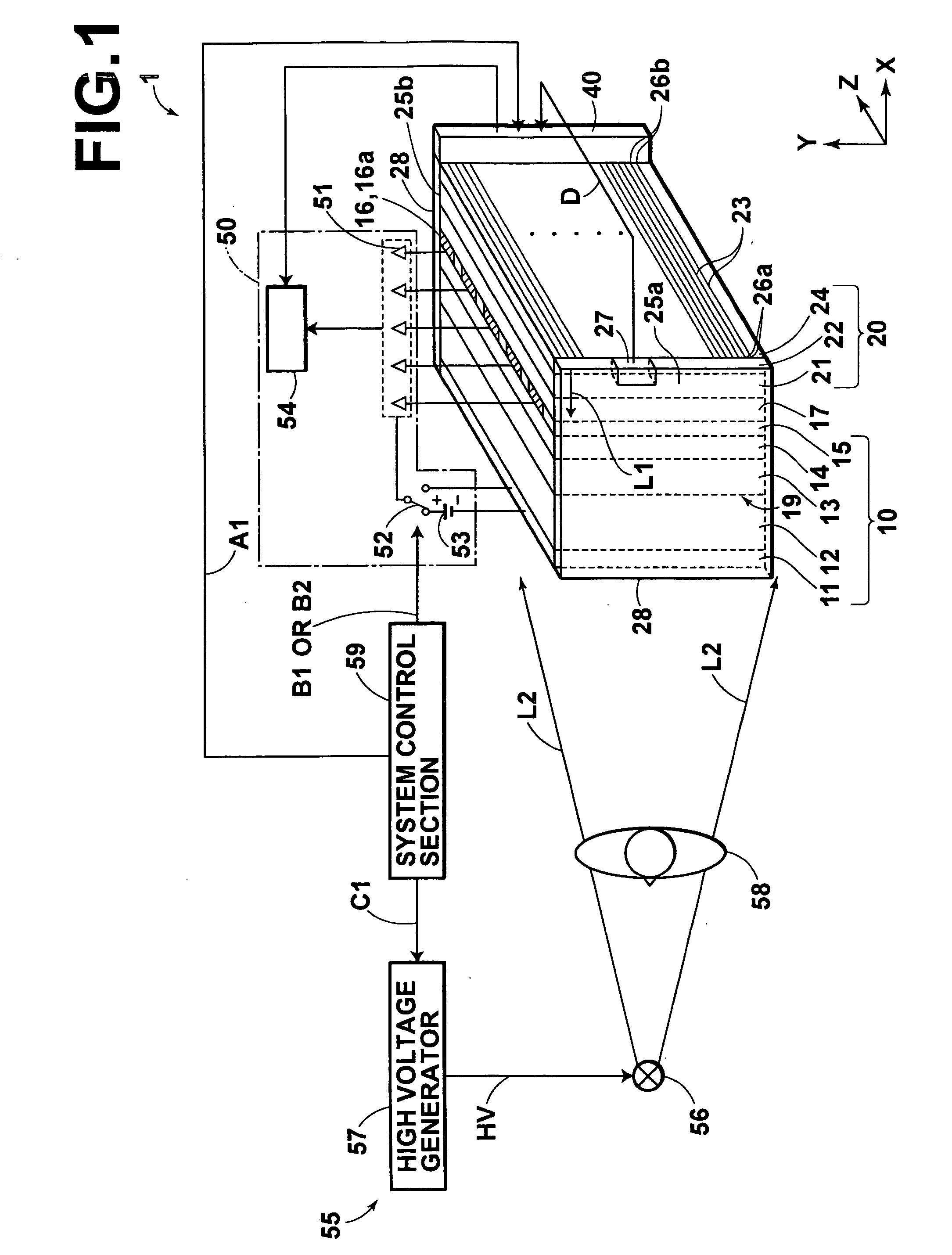
[0135]FIG. 1 is a schematic view showing an image information recording and read-out system, in which the image information read-out apparatus in accordance with the present invention is employed. With reference to FIG. 1, an image information recording and read-out system 1 comprises an image recording medium 10, which is capable of recording an electrostatic latent image having a size of 430 mm×430 mm thereon. The image information recording and read-out system 1 also comprises a panel-shaped light source section 20, which performs scanning exposure of the image recording medium 10 with reading light beams L1, L1, . . . The image information recording and read-out system 1 further comprises a scanning exposure control section 40, which controls an operation of the panel-shaped light source section 20. The image information recording and read-out system 1 still further comprises a reading section 50, which reads the image information from the image recording medium 10. The image in...

fourth embodiment

[0192] In the fourth embodiment, as the cumulative period of actuation of the EL layer 22 becomes long, the electric current flowing across the EL layer 22 is successively set to be high, such that the lowering of the optical intensity of the light radiated out from the EL layer 22 may be compensated for. Therefore, regardless of the cumulative period of actuation of the EL layer 22, the light having approximately predetermined optical intensity is capable of being radiated out from the EL layer 22.

[0193] The operations of the image information recording and read-out system 4 are basically identical with the operations of the image information recording and read-out system 1 described above, except for the technique for controlling the optical intensity of each of the reading light beams L1, L1, . . .

[0194] As described above, with the fourth embodiment, as in the first embodiment described above, the problems are capable of being prevented from occurring in that, as the cumulative...

fifth embodiment

[0200] For each read-out scanning operation, as the image correction data, the correction data forming section 78 calculates a ratio F of the optical intensity of the light, which is radiated out from the EL layer 22 in cases where the cumulative period of actuation of the EL layer 22 is zero, to the optical intensity of the light, which is radiated out from the EL layer 22 at the time of the read-out operation. The ratio F is calculated from the cumulative period of actuation of the EL layer 22, which cumulative period of actuation has been stored in the cumulative actuation period storing section 76, and the aging characteristics of the equivalent EL layer, which aging characteristics have been stored in the storage section 77. Also, the image information correcting section 79 multiplies each of pixel values of the image information, which has been read out from the image recording medium 10, by the ratio F. In this manner, the image information correcting section 79 forms the cor...


PUM


Abstract

An EL layer is located between a linear electrode and an opposite electrode, which stands facing the linear electrode, either one of the linear electrode and the opposite electrode being constituted of a light transmissive electrode. Electric power is supplied across the EL layer, which is located between the linear electrode and the opposite electrode, via the linear electrode and the opposite electrode. An optical intensity of light radiated out from the EL layer, across which the electric power has been supplied, is detected. The electric power, which is supplied across the EL layer, is controlled such that the thus detected optical intensity and a predetermined optical intensity, which has been set previously, become approximately identical with each other.

Description

BACKGROUND OF THE INVENTION [0001] 1. Field of the Invention [0002] This invention relates to a line light irradiating method and a line light source device for use in, for example, an operation for irradiating reading light to an image recording medium, on which image information has been recorded, in order to read out the recorded image information from the image recording medium. This invention particularly relates to a line light irradiating method and a line light source device, in which an electroluminescent layer is utilized. This invention also relates to an image information read-out method and apparatus utilizing the line light source device. [0003] 2. Description of the Related Art [0004] Image information recording and read-out systems, in which electrostatic recording materials are utilized, have heretofore been proposed. With the proposed image information recording and read-out systems, such that a radiation dose delivered to an object during a medical X-ray image rec...

Claims


Application Information

Patent Timeline
IPC IPC(8): G01T1/00G21K4/00G01T1/24G03B42/02G03B42/08H01L51/50H04N5/32H05B33/14
CPCG03B42/08
Inventor HAKAMATA, KAZUOIWAKIRI, NAOTO
Owner FUJIFILM HLDG CORP
Why Eureka
Try Eureka