Switching regulator control circuit, switching regulator and switching regulator control method

a technology of switching regulators and control circuits, applied in the direction of power conversion systems, instruments, dc-dc conversion, etc., can solve the problem of inability to follow up changes in load current, and achieve the effect of reducing current consumption

Active Publication Date: 2005-09-29
MONTEREY RES LLC
View PDF6 Cites 8 Cited by
  • Summary
  • Abstract
  • Description
  • Claims
  • Application Information

AI Technical Summary

Benefits of technology

[0008] According to the U.S. Pat. No. 6,127,815, in the suspending period in which no load current flows, the switching timing circuit 101 and the comparator 102 turn to in

Problems solved by technology

In this case, changes in the load current cannot

Method used


Image

  • Switching regulator control circuit, switching regulator and switching regulator control method
  • Switching regulator control circuit, switching regulator and switching regulator control method
  • Switching regulator control circuit, switching regulator and switching regulator control method

Examples


Embodiment Construction

[0026] Hereinafter, the preferred embodiments of the switching regulator control circuit, switching regulator and switching regulator control method of the present invention will be described in detail with reference to FIGS. 1-4.

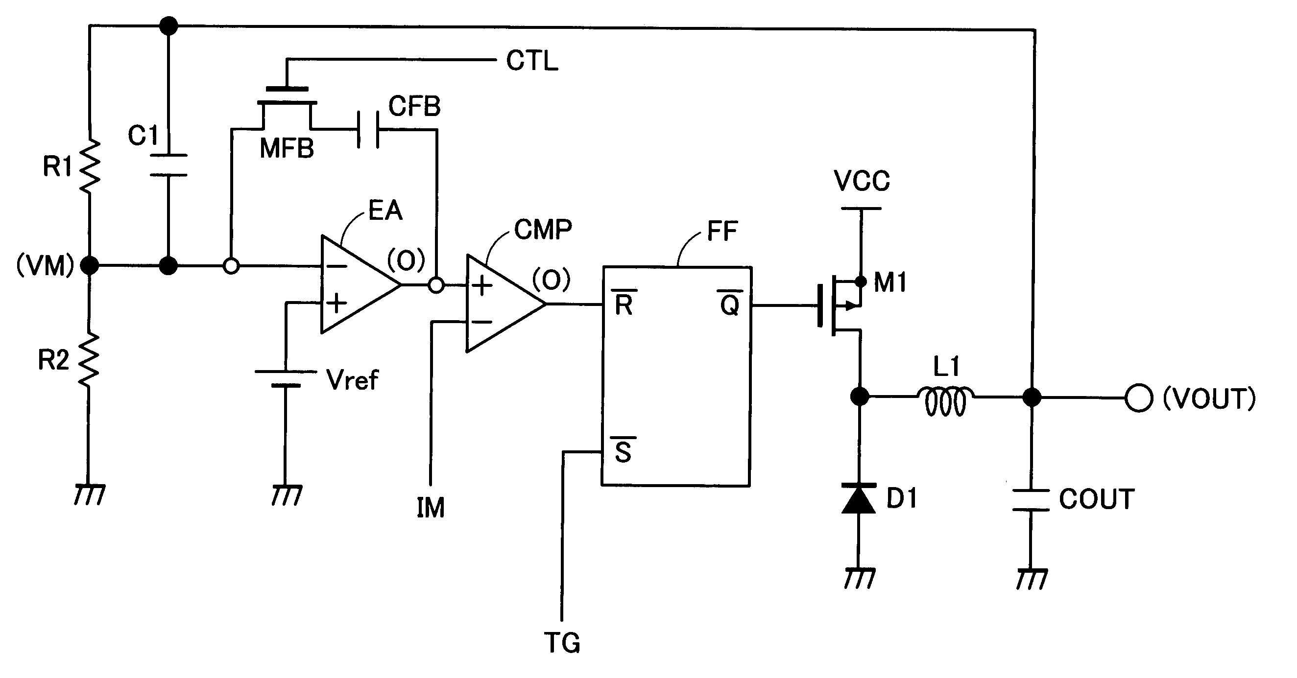
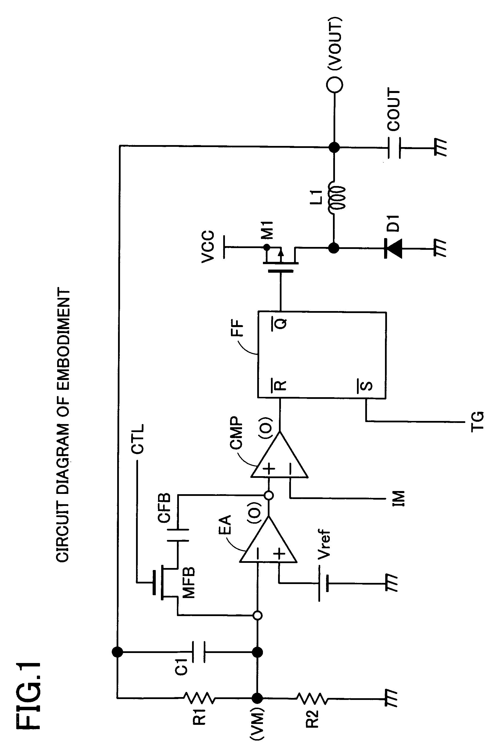
[0027]FIG. 1 shows a step-down switching regulator of the embodiment of the present invention. A load (not shown) is connected to the output terminal (VOUT) and an output capacitor device COUT is connected for supplying charges to the load. Further, resistor devices R1, R2 are connected in series toward a ground potential so as to detect the output voltage VOUT. Further, a capacitor device C1 for phase compensation is connected in parallel to the resistor device R1.

[0028] A connection point (VM) of the resistor devices R1, R2 is a detection point for the output voltage VOUT and connected to an inversion input terminal (−) of the error amplifier EA. A reference voltage Vref is connected to a non-inversion input terminal (+) of the error amplifier EA. The o...


PUM


Abstract

Provides a switching regulator control circuit, a switching regulator and a switching regulator control method for achieving low current consumption and quick response at normal operating time. A change-over switch MFB for opening/closing the phase compensation is provided to establish both the quick responsibility using a gain of an error amplifier EA provided with no phase compensation and stability of control system provided with phase compensation. By turning the change-over switch MFB non-conductive at a timing in which the PMOS transistor M1 turns to conductive, the phase compensation between the input and output of the error amplifier EA is cut off. A detection voltage VM is amplified in term of error with a gain of the error amplifier EA itself. A quick transient response to changes in the output voltage VOUT is achieved corresponding to maximum response characteristic. Phase compensation between the input and output of the error amplifier EA is formed by turning the change-over switch MFB conductive at a timing in which the PMOS transistor M1 turns to non-conductive. Consequently, stability of the control system can be secured.

Description

CROSS-REFERENCE TO RELATED APPLICATIONS [0001] This application is based upon and claims the benefit of priority from each of the prior Japanese Patent Application No. 2004-096511 filed on Mar. 29, 2004, the entire contents of which are incorporated herein by reference. BACKGROUND OF THE INVENTION [0002] 1. Field of the Invention [0003] The present invention relates to a switching regulator and more particularly to a switching regulator having an excellent quick response to a deflection in output voltage despite a low current consumption. [0004] 2. Description of Related Art [0005] The switching regulator disclosed in U.S. Pat. No. 6,127,815 aims at reducing a current consumption to be consumed in a control circuit in a suspending period in which no load current is consumed. In a switching regulator 200 shown in FIG. 5, a sleep signal outputted from a comparator 128 controls a switch 127. Further, a sleep signal is connected to a power saving enable terminal 223 of an error amplifie...

Claims


Application Information

Patent Timeline
IPC IPC(8): G05F1/40H02M3/155G05F1/565H02M3/156H03F1/08
CPCH02M3/156H03F2200/78H03F1/086
Inventor YASUKOUCHI, KATSUYUKI
Owner MONTEREY RES LLC
Why Eureka
Try Eureka