

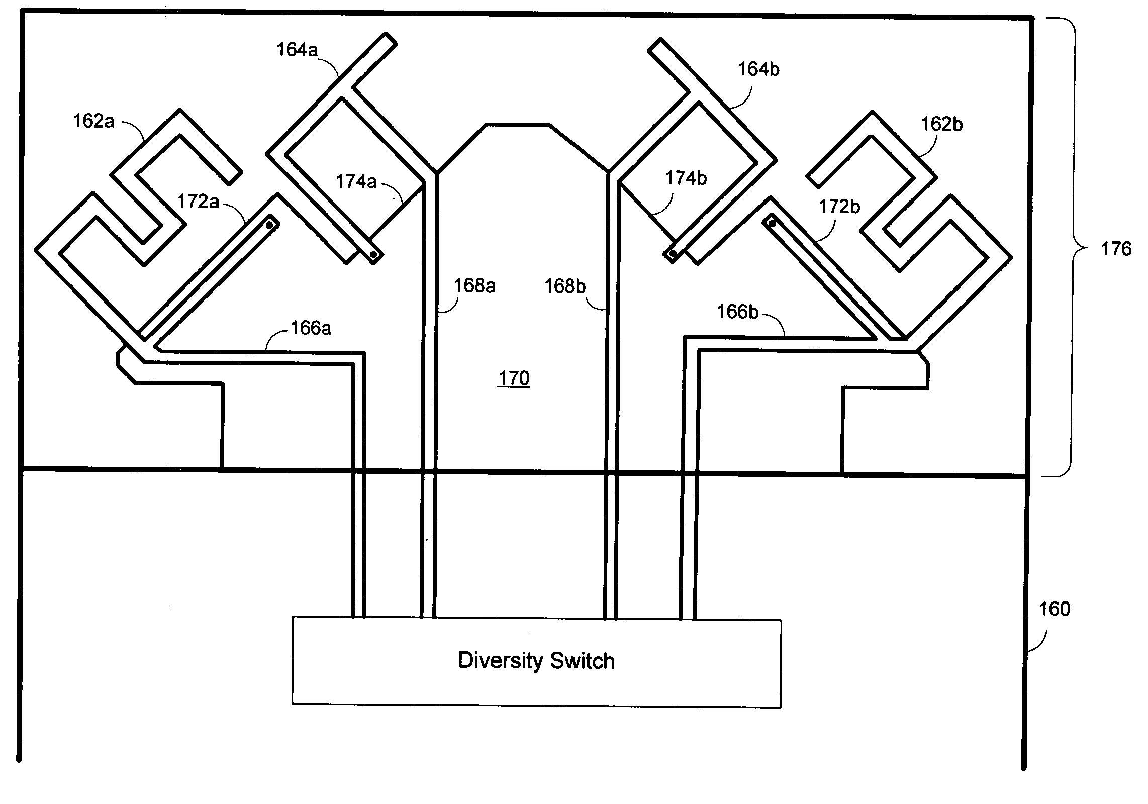
Antenna configuration for wireless communication device
a wireless communication device and antenna configuration technology, applied in the direction of resonant antennas, polarisation/directional diversity, differential interacting antenna combinations, etc., can solve the problems of not providing a system for ensuring the proper orientation of the antenna in the portable wireless communication device, changing the orientation of the antenna used to receive the rf signal, etc., to maximize the signal strength, enhance the gain characteristics of the various antenna elements, and maximize the effect of signal strength
- Summary
- Abstract
- Description
- Claims
- Application Information
AI Technical Summary
Benefits of technology
Problems solved by technology
Method used
Image

Examples
Embodiment Construction
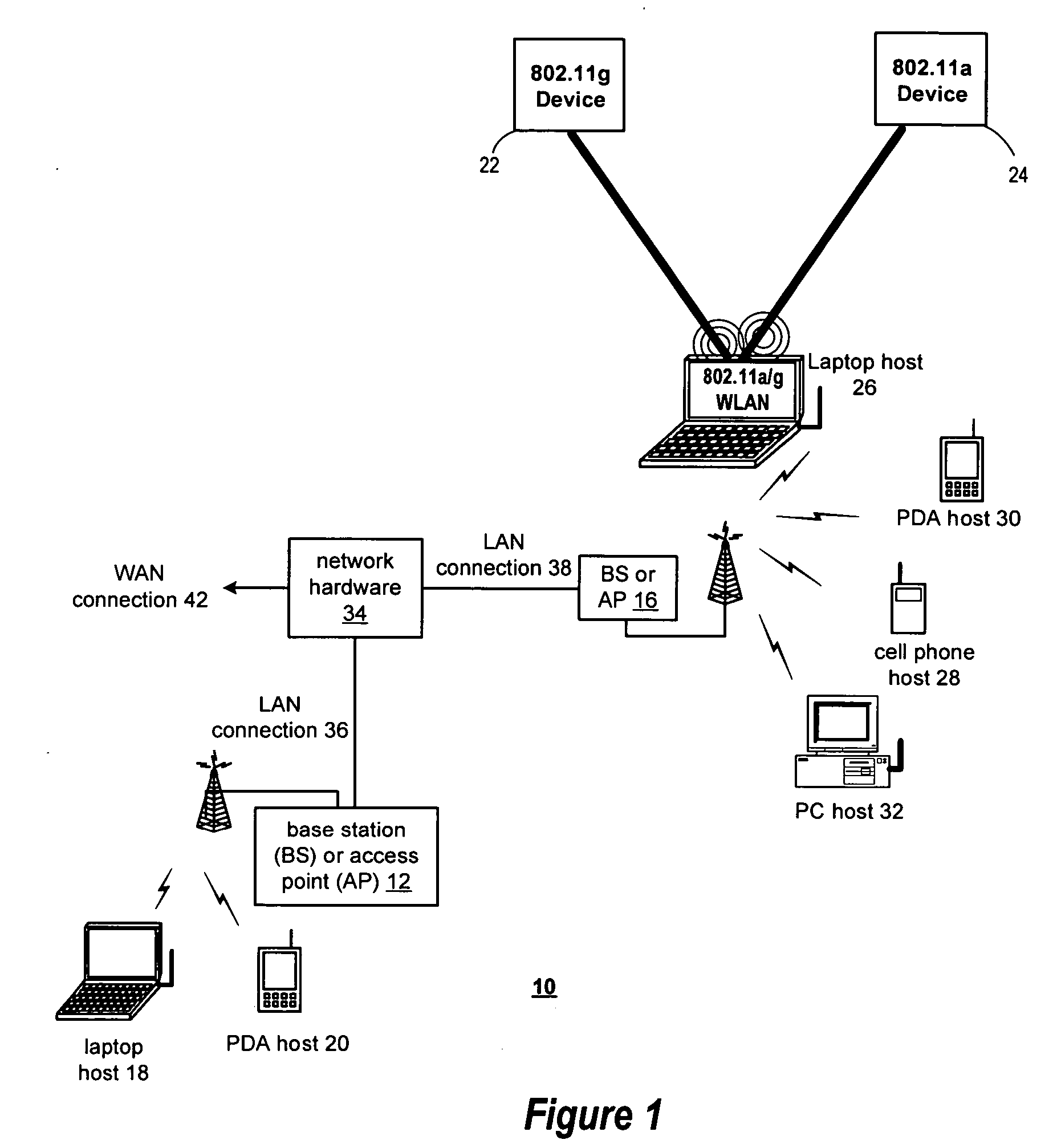
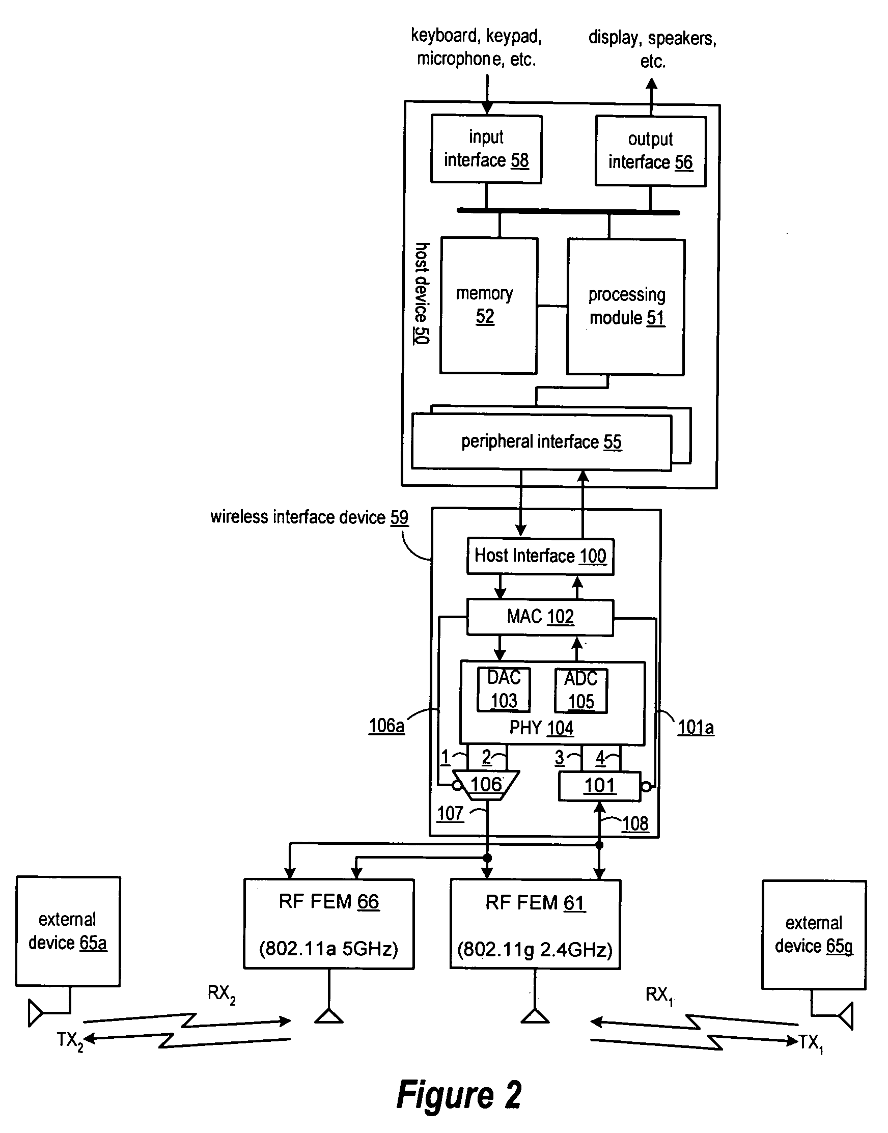
[0020] A method and apparatus for an improved wireless communication system is described. While various details are set forth in the following description, it will be appreciated that the present invention may be practiced without these specific details. For example, selected aspects are shown in block diagram form, rather than in detail, in order to avoid obscuring the present invention. Some portions of the detailed descriptions provided herein are presented in terms of algorithms or operations on data within a computer memory. Such descriptions and representations are used by those skilled in the field of communication systems to describe and convey the substance of their work to others skilled in the art. In general, an algorithm refers to a self-consistent sequence of steps leading to a desired result, where a “step” refers to a manipulation of physical quantities which may, though need not necessarily, take the form of electrical or magnetic signals capable of being stored, tr...
PUM
 Abstract
Description
Claims
Application Information