Method of manufacturing a light guiding panel and an apparatus for the same, and a particle blasting apparatus for manufacturing the light guiding panel

a technology manufacturing method, which is applied in the field of light guiding panel, can solve the problems of degrading optical efficiency, many defections, and complex printing process, and achieve the effect of high brightness and optical efficiency

Inactive Publication Date: 2005-09-29
HUNATECH
View PDF4 Cites 37 Cited by
  • Summary
  • Abstract
  • Description
  • Claims
  • Application Information

AI Technical Summary

Benefits of technology

[0008] It is a first objective of the present invention to provide a light guiding panel manufacturing method by which in order to produce a light guiding panel, minute recesses are for...

Problems solved by technology

In addition, the printing process is complex and many defections may occur during the printing process.
However, since the light transmission factor of a diffusion sheet is usually about 68%, employing a diffusion sheet and the like causes an adverse effect of light loss, the optical efficiency is degraded, and the brightness of the backlight is lowered, accordingly.
However, the market related to manuf...

Method used


Image

  • Method of manufacturing a light guiding panel and an apparatus for the same, and a particle blasting apparatus for manufacturing the light guiding panel
  • Method of manufacturing a light guiding panel and an apparatus for the same, and a particle blasting apparatus for manufacturing the light guiding panel
  • Method of manufacturing a light guiding panel and an apparatus for the same, and a particle blasting apparatus for manufacturing the light guiding panel

Examples


second embodiment

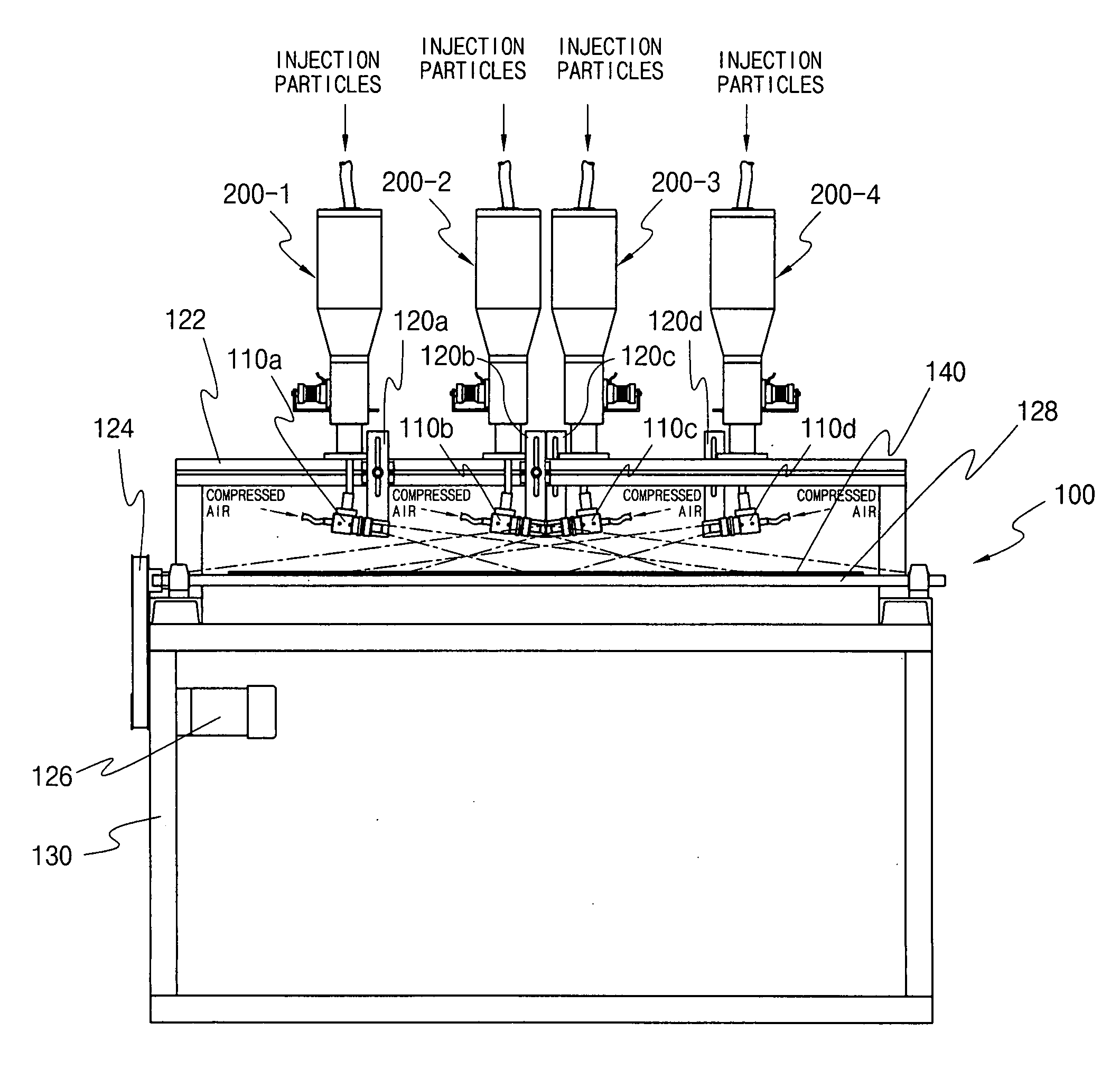
[0071] Next, a second preferred embodiment of a manufacturing apparatus and process of the present invention will now be explained. FIG. 9 is a diagram of a second preferred embodiment of the structure of a light guiding panel manufacturing apparatus according to the present invention. The second embodiment uses perpendicularly and diffusively blasting method using in-lined nozzles. When compared with the manufacturing apparatus shown in FIGS. 3 through 5 described above, this embodiment of the apparatus has no difference in the structure of the transfer apparatus 100 and has a basic difference in that the injection direction is not slanted to the surface of the transparent substrate 140 and is vertical.

[0072] A plurality of injection nozzles 310a through 310i are arranged in a row in the direction perpendicular to the transfer direction of the transfer line on the transfer bars 128. Each injection nozzle 310a through 310i is installed such that the injection is directed right below...

third embodiment

[0080] Next, a third preferred embodiment of the present invention will now be explained. FIGS. 14, 15, and 16 are a side sectional view, a front sectional view, and a plane view, respectively, of the structure of a light guiding panel manufacturing apparatus 500 according to the third preferred embodiment of the present invention. The third embodiment uses a perpendicularly blasting method using a thin funnel-shaped pipe, and the light guiding panel manufacturing apparatus 500 broadly comprises a particle injection apparatus 590 and a transfer apparatus 600.

[0081] The transfer apparatus 600 transfers a transparent substrate 580 in one direction with the transparent substrate 580 placed on the transfer apparatus 600. The transfer apparatus 600 can be implemented as an ordinary conveyer system. More specifically, a pair of guide rails 600f and 600g that are extended in parallel with each other at a predetermined interval are provided and around the outer surfaces of the rails a trans...


PUM

PropertyMeasurementUnit
Timeaaaaaaaaaa
Thicknessaaaaaaaaaa
Pressureaaaaaaaaaa

Abstract

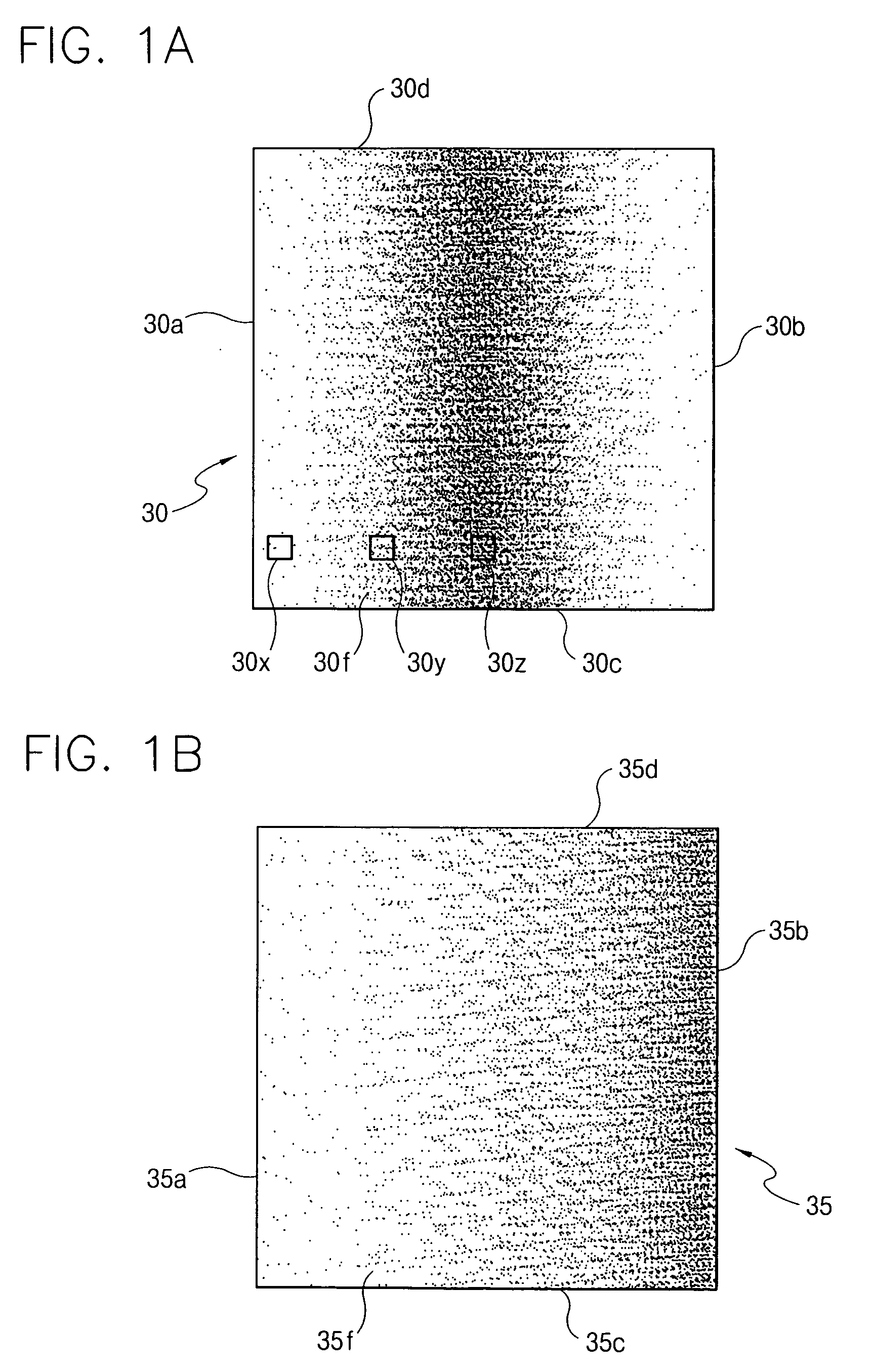
Disclosed are a method of manufacturing a light guiding panel by means of carving fine engravings on a surface of a transparent substrate by plasting fine particles and an apparatus for the same. A distributed degree of the engravings gradually increases as they become far away from a light source position. In a first method, fine particles are mixed with a high-speed air and then the air-mixed fine particles are diffusively blasted through one or more blasting nozzles so that the fine particles can collide with a surface of a transparent substrate slantly. In a second method, the air-mixed fine particles are diffusively blasted through a plurality of aligned blasting nozzles so that the fine particles can perpendicularly collide with the entire width of a transparent substrate, while appropriately adjusting intervals of the blasting nozzles and/or the amount of blasting as well as swing the blasting nozzles. In a third method, fine particles are mixed with an air generated by a high-speed rotating blower and then the air-mixed fine particles are blasted through a flat funnel-shaped blasting pipe having an outlet of which the width is not narrower than that of the transparent substrate to perpendicularly collide with a transparent substrate. The cross-sectional shape of the outlet of the blasting pipe can be varied by a user's control. The blasting amount of the fine particles is constantly maintained with respect to time by means of a free fall feeding manner of the fine particles. The light guiding panel which has been so manufactured does not need a diffusion sheet and has a good brightness uniformity and a good light effectiveness.

Description

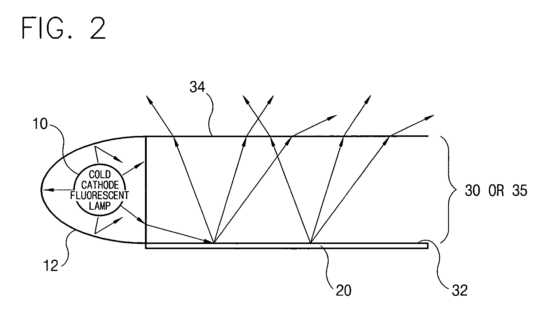
TECHNICAL FIELD [0001] The present invention relates to a light guiding panel, and more particularly, to a method and an apparatus for manufacturing a light guiding panel and a particle blasting apparatus for the same. BACKGROUND ART [0002] A light guiding panel is one of core elements forming a backlight unit. The backlight unit converts light of a tube lamp into light of flat optical sources and is widely used in an apparatus, such as a liquid crystal display (LCD) panel or an advertising display apparatus, which requires a flat light source. [0003] Methods for forming a backlight unit are broken down to a direct-type method and a light guiding panel method according to the location of an optical source. The direct-type method places the optical source directly below a light emitting surface so as to guarantee planar light emission, while the light guiding panel method places an optical source at a side of a light guiding panel so that light which is incident on the side of the pa...

Claims


Application Information

Patent Timeline
IPC IPC(8): G02B6/00B29C59/00B29L7/00B29L11/00F21V8/00G02F1/13G02F1/13357
CPCG02B6/0065G02F1/1335
Inventor MYOUNG, BUM YOUNG
Owner HUNATECH
Why Eureka
Try Eureka