Tapered roller bearing

Active Publication Date: 2005-09-29
JTEKT CORP
View PDF5 Cites 11 Cited by
  • Summary
  • Abstract
  • Description
  • Claims
  • Application Information

AI Technical Summary

Benefits of technology

[0016] In the tapered roller bearing according to the present invention, since the labyrinth is defined between the cage and the inner race which define the oil inlet section, an oil inflow into the tapered roller bearing is reduced, whereby agitation resistance of the oil and torque loss of the tape

Problems solved by technology

However, when compared to a ball bearing, the tapered roller bearing suffers from a larger torque loss.
In particular, in the case of a tapered roller bearing which is used at a high rotational speed, the resistance by agitation of the lubricant oil occ

Method used


Image

  • Tapered roller bearing
  • Tapered roller bearing
  • Tapered roller bearing

Examples


Example

First Embodiment

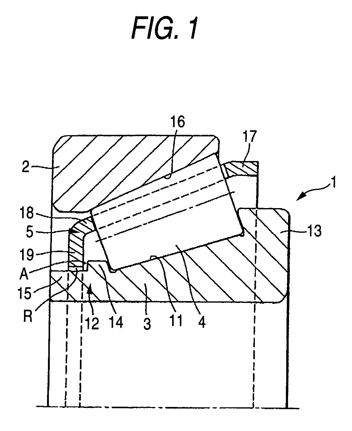
[0025] A tapered roller bearing 1 in accordance with an embodiment of the present invention which is shown in FIG. 1 includes an outer race 2, an inner race 3, a plurality of tapered rollers 4 which are interposed between the outer race 2 and the inner race 3, and a cage 5 for retaining the tapered rollers 4.

[0026] The inner race 3 has a tapered raceway 11, a small-diameter end portion 12 which is formed at the left end of the raceway 11, and a large-diameter end portion 13 which is formed at the right end of the raceway 11. The small-diameter end portion 12 of the inner race 3 has a small flange portion 14 for limiting axial movement of the tapered rollers 4 and a cylindrical portion 15 which has a less diameter than the small flange portion 14 and is connected to the axial outer end of the small flange portion 14. The large-diameter end portion 13 of the inner race 3 has a large flange portion for limiting axial movement of the tapered rollers 4.

[0027] The oute...

Example

Second Embodiment

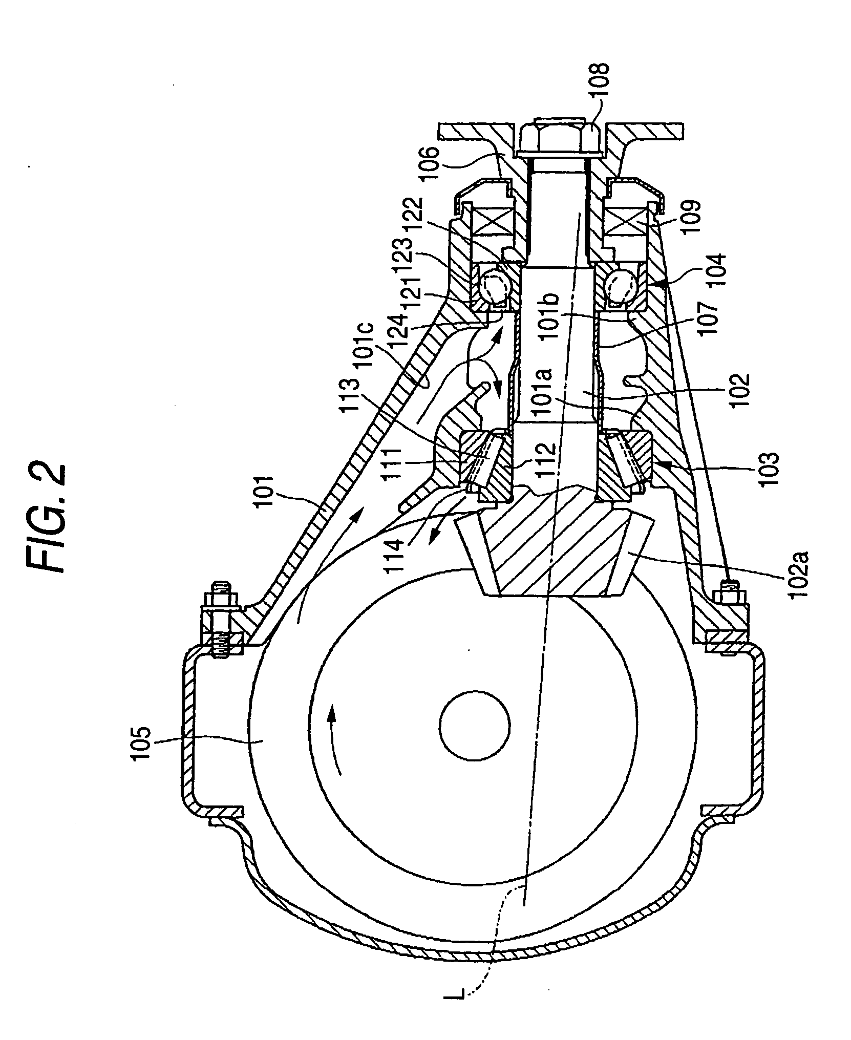
[0030] The tapered roller bearing according to the present invention can be suitably employed for rotatably supporting a pinion shaft with respect to a differential carrier or for rotatably supporting a differential case with respect to a differential carrier, in a final reduction gear of an automotive vehicle having a final gear or a differential gear.

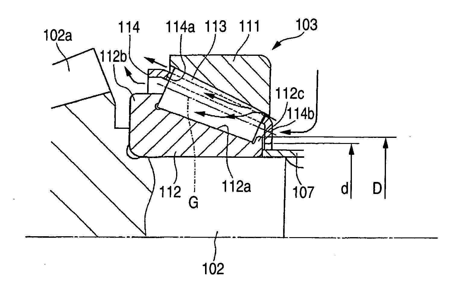
[0031] Hereinbelow, an example in which the tapered roller bearing according to the present invention is applied to a differential gear will be described in detail with reference to FIGS. 2 through 4. FIG. 2 is a cross-sectional view illustrating a differential according to the present invention; FIG. 3 is an enlarged cross-sectional view illustrating a bearing device of FIG. 1, for supporting a pinion shaft; and FIG. 4 is an enlarged cross-sectional view illustrating a tapered roller bearing of FIG. 3, which is positioned adjacent to the pinion shaft.

[0032] A bearing device for supporting a pinion shaft of a diff...


PUM


Abstract

A tapered roller bearing comprises an outer race, an inner race, a plurality of tapered rollers, and a cage. A small-diameter end portion of the inner race is formed with a small flange portion for limiting axial movement of the tapered rollers and a cylindrical portion which has a less diameter than the small flange portion and is connected to an axial outer end of the small flange portion. The cage is formed at a small-diameter end portion thereof with a bent portion which is bent inward in a radial direction. A small-diameter end portion of the cage has a bent portion which is faced to an outer surface of the cylindrical portion of the inner race with a predetermined clearance therefrom such that a labyrinth is created between the cage and the inner race.

Description

BACKGROUND OF THE INVENTION [0001] The present invention relates to a tapered roller bearing, and more particularly, to a tapered roller bearing which is arranged in a final reduction gear of an automotive vehicle, etc. and is lubricated using oil accommodated in the final reduction gear, and a bearing device for supporting a pinion shaft, which supports the pinion shaft using two inclined contact type rolling bearings disposed in a housing. [0002] A tapered roller bearing which is provided with an outer race, an inner race, a plurality of tapered rollers interposed between the outer race and the inner race, and a cage for retaining the tapered rollers has been widely used since it is compact, stands large radial and axial loads and is suitable for high speed rotation. However, when compared to a ball bearing, the tapered roller bearing suffers from a larger torque loss. Therefore, in view of energy utilization efficiency, it is necessary to decrease a torque loss of the tapered rol...

Claims


Application Information

Patent Timeline
IPC IPC(8): B60B27/00F16C19/16F16H48/08F16C19/36F16C19/54F16C33/46F16C33/54F16C33/66F16C35/06F16H48/38F16H57/021F16H57/037F16H57/038F16H57/039F16H57/04
CPCF16C19/364F16C19/54F16C33/543F16C33/6651F16C33/6674F16C2240/40F16C2361/61F16H57/037F16H57/0421F16H57/0471F16H57/0483F16H2048/423F16H57/021
Inventor ONO, KENICHIYOKOTA, KUNIHIKOTACHI, HIROSHI
Owner JTEKT CORP
Why Eureka
Try Eureka