Optical battery temperature monitoring system and method

a temperature monitoring and battery technology, applied in the field of monitoring and controlling systems, can solve the problems of not giving the true temperature of the battery system, and the limitation of being able to measure only the external temperature, and achieve the effect of efficient monitoring and controlling the battery system

Active Publication Date: 2005-09-29
GENERAL ELECTRIC CO
View PDF6 Cites 47 Cited by
  • Summary
  • Abstract
  • Description
  • Claims
  • Application Information

AI Technical Summary

Benefits of technology

[0012] It would therefore be desirable to obtain true temperature measurement of the battery system. Also desi

Problems solved by technology

However, these do not give the true temperature of the battery system.
Again, th

Method used


Image

  • Optical battery temperature monitoring system and method
  • Optical battery temperature monitoring system and method
  • Optical battery temperature monitoring system and method

Examples


Embodiment Construction

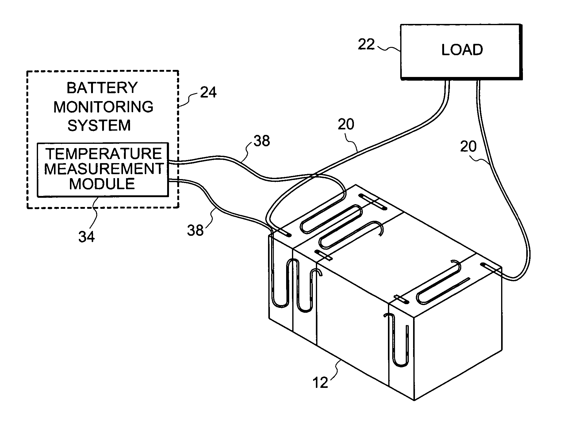
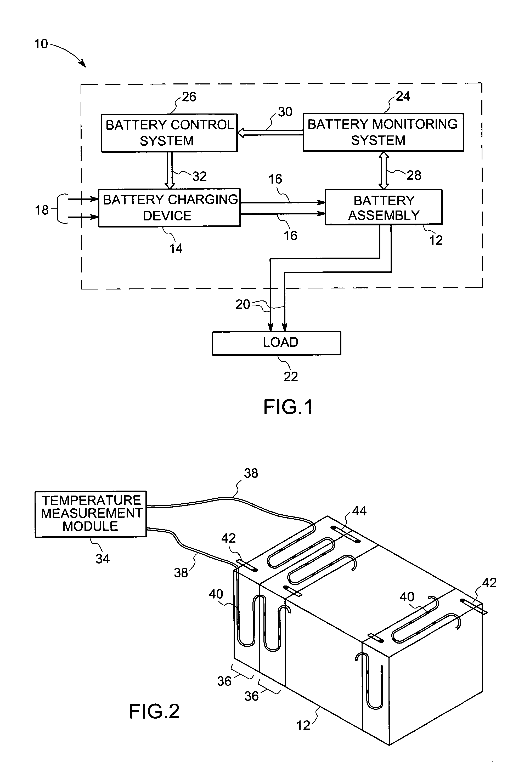
[0022]FIG. 1 is a diagrammatical view of an exemplary battery temperature monitoring and control system, designated generally by numeral 10. The system 10 of FIG. 1 is adapted to obtain a temperature profile of a battery assembly 12, and optionally, to control the battery charging mechanism based on the measured temperature. The battery assembly 12 as illustrated in FIG. 1 contains several individual cells.

[0023] A battery charging device 14 charges the battery assembly 12, via leads 16. The batter charging device 14, itself, received power from an external source, such as via leads 18. The battery assembly 12 is also coupled to leads 20, and thereby, to a load 22 by leads 20. The load could be any system utilizing high capacity battery power supply. The battery assembly 12 is furthermore coupled to a battery monitoring system 24 that monitors the temperature of individual cells or locations in the battery assembly 12. Where desired, and as shown in FIG. 1, the battery monitoring s...


PUM


Abstract

Several methods for measuring and monitoring temperature have been presented for systems requiring temperature monitoring. In one implementation, the system has been applied to battery assemblies. Temperature measurements for every part of the battery assembly are disclosed. In one aspect the surface temperature of a battery assembly is measured. In another aspect, the internal temperature of the battery assembly is measured. In other aspects, the internal and external temperatures of several battery assemblies are measured. Based on the measured temperature, control signals are generated by a control system to switch down the power of the battery charging system so as to prevent excess heat generation.

Description

BACKGROUND [0001] The invention relates generally to monitoring and control systems and more particularly to a method and system for monitoring a temperature of batteries. [0002] A wide variety of applications employ batteries and battery banks for operation. These range from mobile applications to consumer uses to industrial applications, to mention just a few. Vehicle and other mobile applications, for example, commonly use one or more batteries either for starting and auxiliary functions, or for a primary or secondary source of power for normal operation. In recent years, for example, electrical vehicles and hybrid electrical / engine driven vehicles have become the focus of intense development activities. Such vehicles represent a demanding environment in which battery performance and life are important to the continued reliable operation of the vehicular systems. [0003] Battery systems used in many applications, such as electrical and hybrid vehicles, may contain many battery mod...

Claims


Application Information

Patent Timeline
IPC IPC(8): G01K11/32G01R31/36G02B6/00
CPCG01R31/3675G01K11/32H01M10/443H01M10/486G01R31/374Y02E60/10
Inventor RAJENDRAN, VEERA PALANIVELUKING, ROBERT DEANRICHTER, TIMOTHY GERARDSALASOO, LEMBIT
Owner GENERAL ELECTRIC CO
Why Eureka
Try Eureka