Wavelength division multiplexing optical transmission system and wavelength dispersion compensation unit

a wavelength division multiplexing and optical transmission technology, applied in wavelength-division multiplex systems, optical waveguide light guides, multi-component communication, etc., can solve the problems of deteriorating transmission quality, dispersion exceeding a tolerable dispersion value, and inability to completely compensate the wavelength dispersion produced in the optical fiber transmission line, etc., to achieve efficient dispersion compensation, simple configuration, and efficient compensating residual dispersion

Active Publication Date: 2005-09-29
FUJITSU LTD
View PDF14 Cites 4 Cited by
  • Summary
  • Abstract
  • Description
  • Claims
  • Application Information

AI Technical Summary

Benefits of technology

[0020] Thus, when compensating the wavelength dispersion in an optical transmission line of an wavelength division multiplexing optical transmission system using a high-slope dispersion compensation unit such as a high-slope DCF, it becomes possible to compensate residual dispersion efficiently with a simple configuration by grouping the wavelength bandwidth into a plurality of groups, and by compensating the residual dispersion for each group.
[0021] In particular, from the dispersion compensation characteristic of the high-slope dispersion compensation unit, the wavelength dispersion magnitude of both end sides of the wavelength bandwidth becomes the same order. By using a three-port bandpass filter enabling collective extraction of both end sides of the wavelength bandwidth, it becomes possible to perform the dispersion compensation based on the demultiplexing with the number of groups less than the number of wavelength bandwidth groups, and thus dispersion compensation can be attained more efficiently at reduced cost.

Problems solved by technology

In such high-speed optical transmission systems, an optical transmission signal waveform in an optical fiber transmission line is deteriorated by a wavelength dispersion characteristic of the transmission line, causing deterioration of the transmission quality.
Accordingly, when using the conventional DCF, it is not completely possible to compensate the wavelength dispersion produced in the optical fiber transmission line.
When the optical fiber transmission line has a long distance, undesirably the dispersion exceeds a tolerable dispersion value because of the accumulated residual dispersion.
On the other hand, if the wavelength dispersion compensation is performed to meet the wavelength dispersion magnitude on the long wavelength region, the compensation magnitude in the short wavelength bandwidth becomes excessively large, which undesirably exceeds the tolerable dispersion value on the inverse sign side.
However, to apply different DCFs for each wavelength makes the configuration of wavelength dispersion compensation unit 32 complicate, which produces an increased cost.
However, a residual dispersion characteristic (c) of convex arc shape still remains, which leads to deterioration of transmission quality when the residual dispersion magnitude exceeds the tolerable dispersion value even in this case.
If the residual dispersion magnitude exceeds in any portion of the wavelength bandwidth, the transmission quality is deteriorated.

Method used


Image

  • Wavelength division multiplexing optical transmission system and wavelength dispersion compensation unit
  • Wavelength division multiplexing optical transmission system and wavelength dispersion compensation unit
  • Wavelength division multiplexing optical transmission system and wavelength dispersion compensation unit

Examples


Embodiment Construction

[0037] The preferred embodiment of the present invention is described herein after referring to the charts and drawings. However, it is noted that the scope of the present invention is not limited to the embodiments described below.

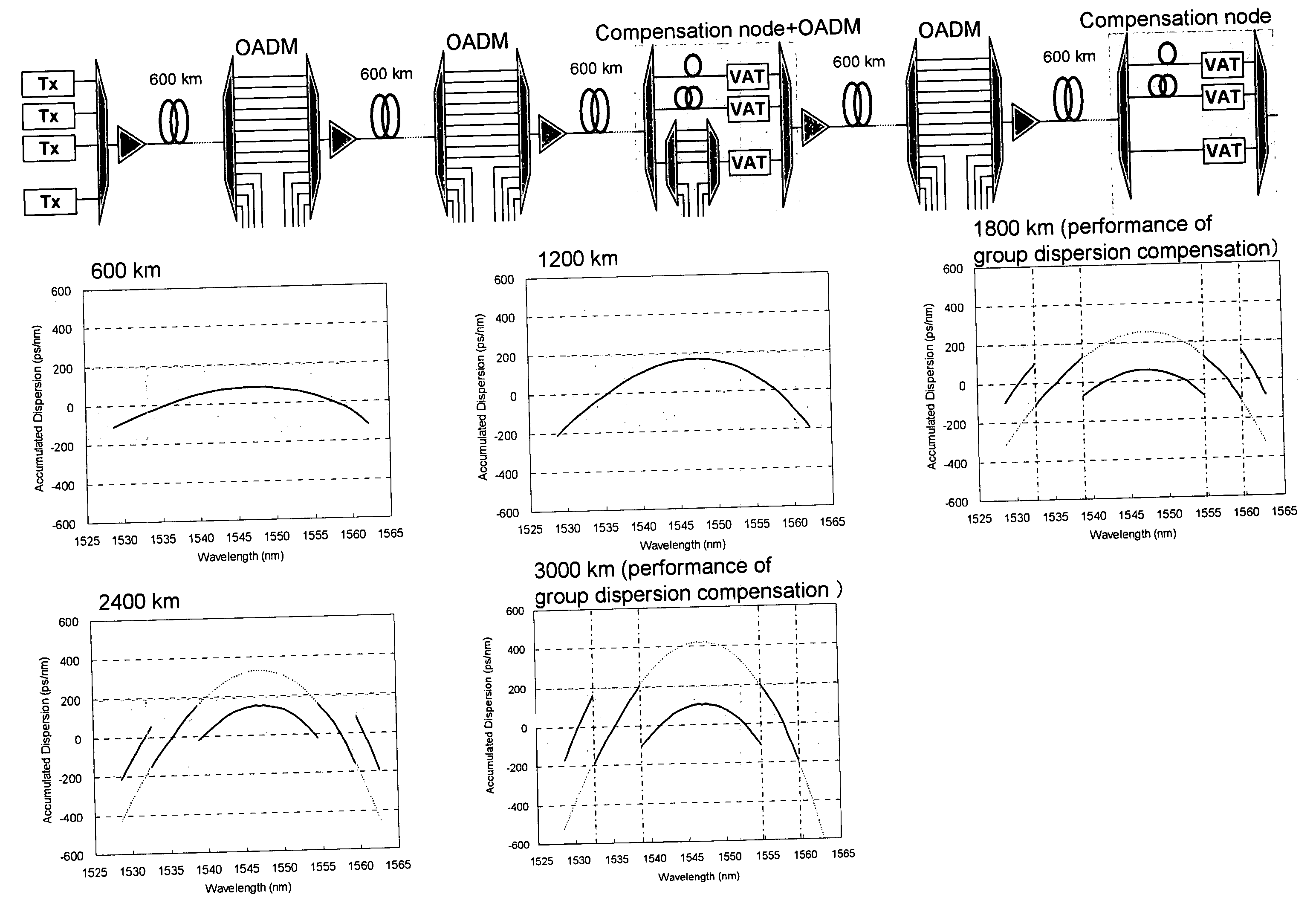
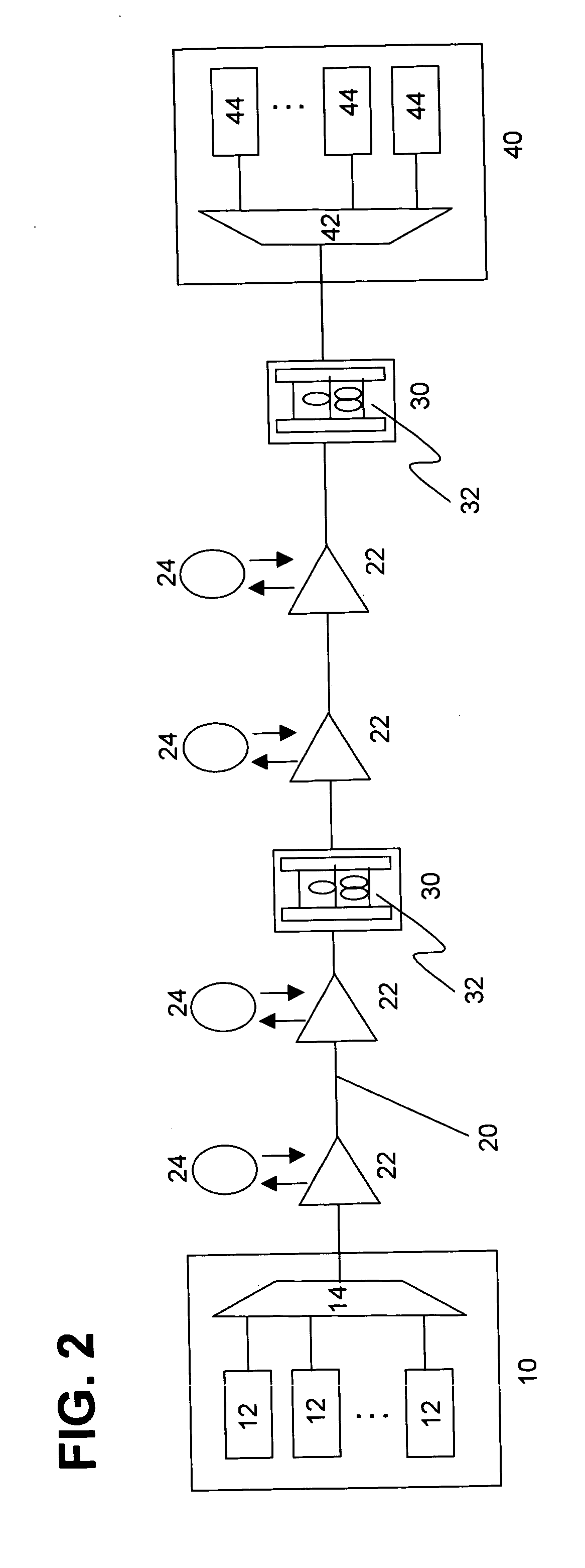
[0038] The following describes, in the wavelength division multiplexing optical transmission system shown in FIG. 2 according to the embodiments of the present invention, a wavelength dispersion compensation unit 32 for compensating accumulated residual dispersion, when the aforementioned high-slope dispersion compensation fiber (DCF) is employed for dispersion compensation to be performed in each optical repeater 22. Wavelength dispersion compensation unit 32 in the embodiment of the present invention divides the wavelength bandwidth of a wavelength-multiplexed signal into a plurality of groups, and collectively compensates the residual dispersion of a plurality of channel signals included in each group.

[0039]FIG. 5 shows a diagram illustrating an exam...


PUM


Abstract

In the WDM optical transmission system, a high-slope dispersion compensator compensates wavelength dispersion produced in the optical transmission line. The high-slope dispersion compensator has a dispersion slope characteristic, by which a dispersion slope is substantially compensated over the wavelength bandwidth of the optical transmission line, and also a dispersion compensation characteristic, by which the residual dispersion produced after compensating the dispersion slope using the above dispersion slope characteristic becomes symmetrical with respect to a wavelength in the vicinity of the center of the wavelength bandwidth. To achieve the above compensation, a wavelength-multiplexed signal is divided into wavelength bandwidth groups, and the residual dispersion of the optical transmission line is compensated on a group-by-group basis for the wavelength bandwidth groups.

Description

FIELD OF THE INVENTION [0001] The present invention relates to a wavelength division multiplexing optical transmission system transmitting a wavelength division multiplexed signal from a transmitting side to a receiving side through an optical transmission line, and more particularly, in case that wavelength dispersion of the optical transmission line in the wavelength division multiplexing optical transmission system is compensated by a high-slope dispersion compensation unit having a dispersion slope capable of substantially compensating a wavelength dispersion slope in a wavelength bandwidth of the optical transmission line, and also having a dispersion compensation characteristic obtained by the aforementioned dispersion slope, such that residual dispersion after compensating the wavelength dispersion slope becomes substantially symmetrical with respect to a wavelength in the vicinity of the center of the wavelength bandwidth, a wavelength dispersion compensation unit for compen...

Claims


Application Information

Patent Timeline
Patent Type & Authority Applications(United States)
IPC IPC(8): H04B10/2507G02B6/10H04B10/2525H04J14/00H04J14/02
CPCH04B10/2525H04J14/0213H04J14/02
Inventor NAKAMURA, KENTAROOOI, HIROKIISHIKAWA, GEORGE
Owner FUJITSU LTD
Why Eureka
Try Eureka