Arrayed receiver optical sub-assembly including layered ceramic substrate for alleviation of cross-talk and noise between channels

a receiver and optical sub-assembly technology, applied in the field of receiver optical sub-assemblies, can solve the problems of internal crosstalk and noise-induced degradation of individual channel data signals, difficult to locate a ground plane close enough to connect the tia input ground pads, and the inability to detect the input of the tia

Inactive Publication Date: 2005-09-29
OPTICAL COMM PRODS
View PDF1 Cites 32 Cited by
  • Summary
  • Abstract
  • Description
  • Claims
  • Application Information

AI Technical Summary

Problems solved by technology

A tightly packaged array of parallel data channels such as this can introduce crosstalk and noise-induced degradation of the individual channel's data signal from several sources over different paths.
An additional complication related to arrays is the mutual inductance of signal wire bonds that are in close proximity.
Internal crosstalk between data channels at the input of the TIA may also present a significant problem.
However tight packing requirements and the close proximity of the detector array make it difficult to locate a ground plane close enough to connect the TIA input ground pads.
Furthermore, the TIA signal output power is low, relative to that of the post-amplifier.
The high number of differential pair outputs packed in a small area are especi...

Method used


Image

  • Arrayed receiver optical sub-assembly including layered ceramic substrate for alleviation of cross-talk and noise between channels
  • Arrayed receiver optical sub-assembly including layered ceramic substrate for alleviation of cross-talk and noise between channels
  • Arrayed receiver optical sub-assembly including layered ceramic substrate for alleviation of cross-talk and noise between channels

Examples


Embodiment Construction

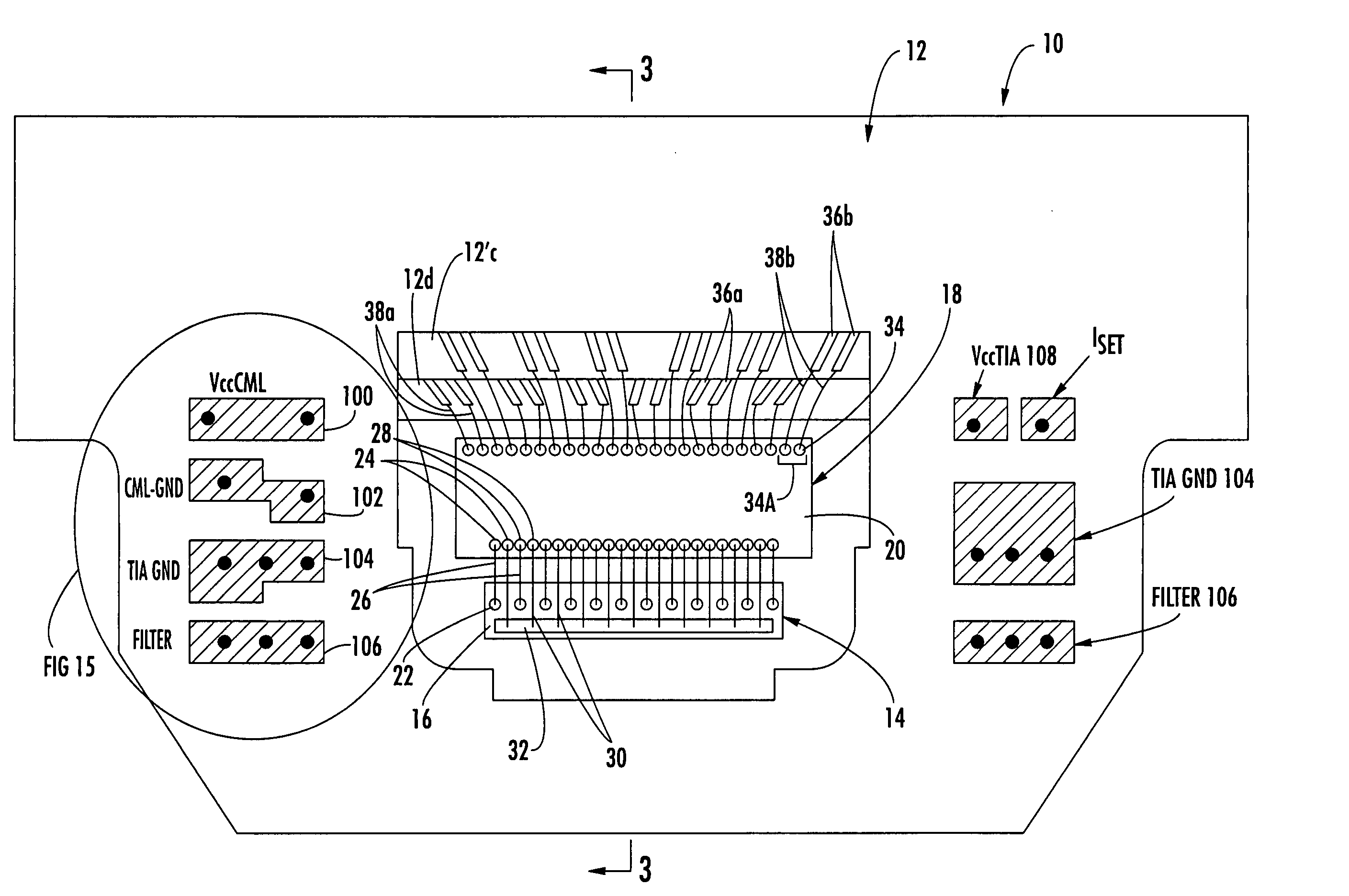
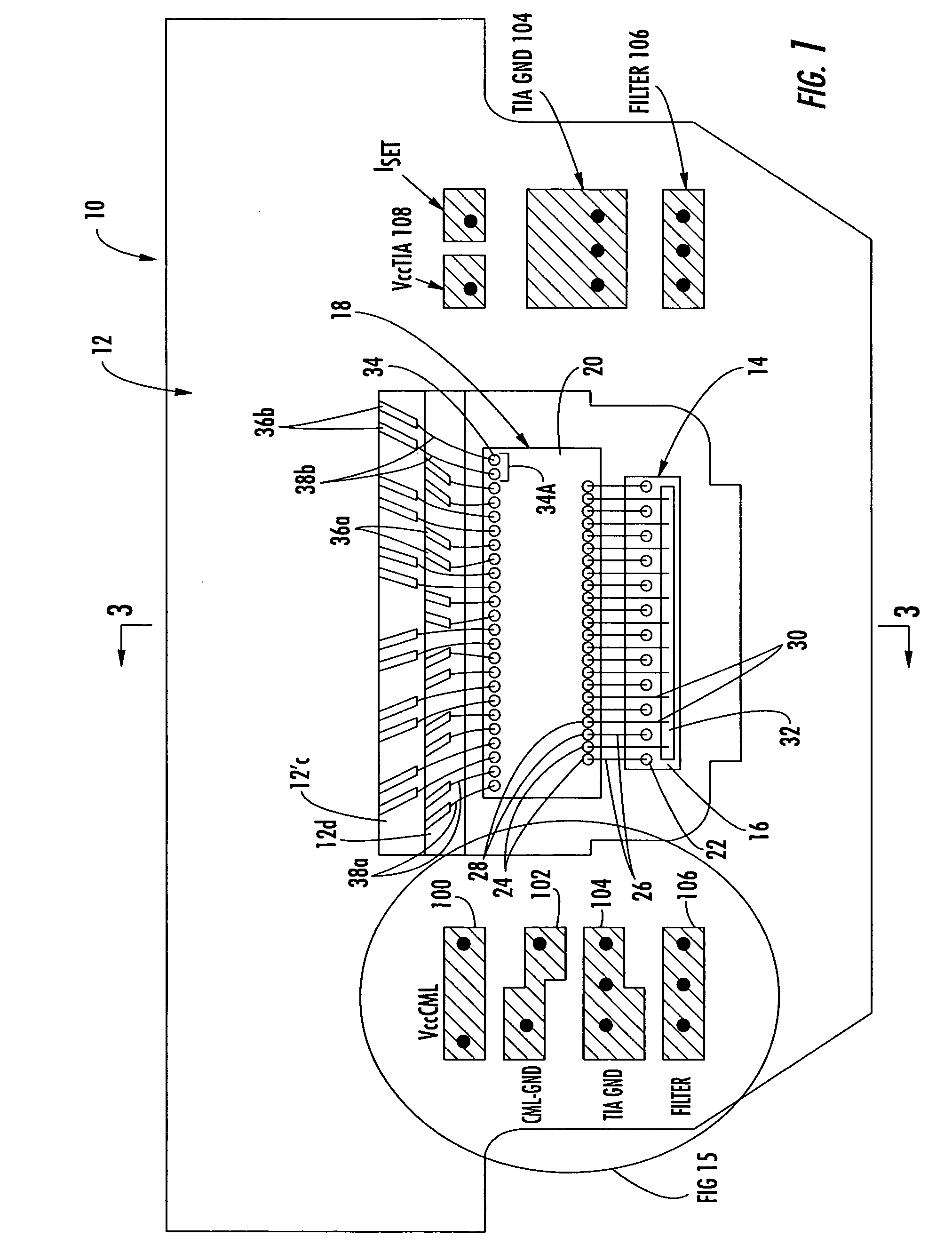
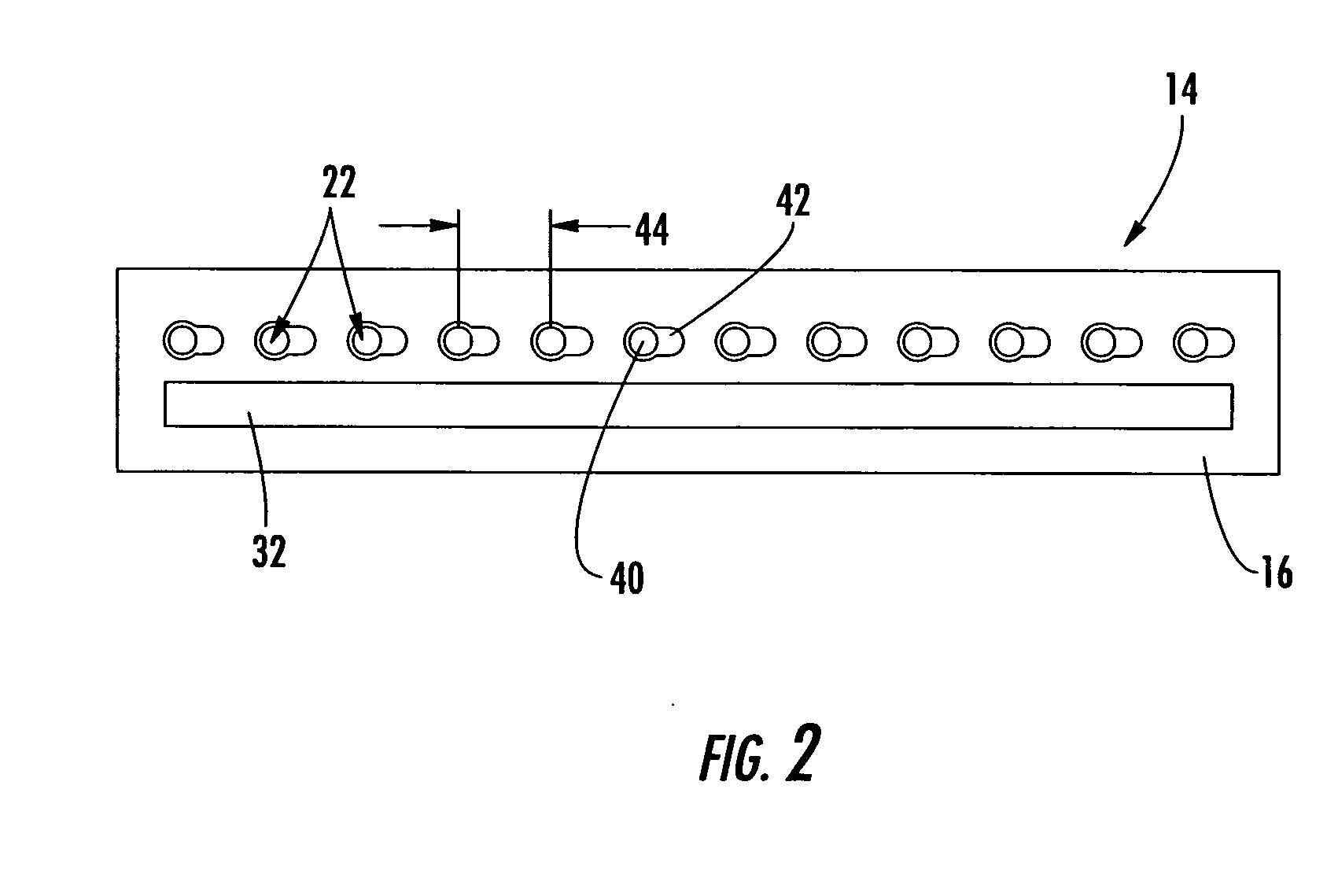
[0021] Referring now to the drawings, FIGS. 1-4 illustrate an exemplary embodiment of the present invention which provides a ROSA (receiver optical sub-assembly) 10 including a multi-layer ceramic substrate 12, a photodetector array 14 grown monolithically on a photodetector substrate 16, and a corresponding transimpedance amplifier (TIA) array 18 grown on a separate substrate 20, both of which are attached to the multilayer ceramic substrate 12.

[0022] The photodetector array 14 includes a plurality of photodetectors 22 which are coupled to input pads 24 of the TIA array 18 by conductive wire bonds 26. According to one exemplary embodiment, ground pads 28 may be formed between adjacent input pads 24 of the TIA array 18. Each of the ground pads 28 may be individually and directly coupled by a wire bond 30 to an isolated ground strip 32 formed opposite the photodetector array 14 and on the same photodetector substrate 16. The isolated strip 32 is then connected, via a number of wire ...


PUM


Abstract

A receiver optical subassembly (ROSA) includes a photodetector array and a transimpedance amplifier (TIA) array. In each data channel, the photodetector is wire bonded to a corresponding input pad of the TIA array. A ground pad is disposed between adjacent input pads and connected to a ground plane via an isolated bonding strip on the photodetector array in order to alleviate crosstalk between the channels. The output data channels of the TIA are tightly spaced at the output pads of the TIA and are fanned out on the ceramic to increase the spacing of the data channels as they extend from the TIA. The ROSA includes the use of embedded capacitance to reduce crosstalk and noise by decoupling reference planes formed within the multilayer ceramic substrate. Input and output ground planes of the TIA are separated in the vicinity of the TIA and coupled on a ceramic layer spaced farther from the TIA, to alleviate crosstalk.

Description

BACKGROUND OF THE INVENTION [0001] The instant invention relates, most generally, to receiver optical sub-assemblies (ROSA's). More particularly, the present invention is related to the alleviation of cross-talk between channels of an arrayed ROSA and the reduction of noise in the arrayed ROSA. [0002] ROSA's (receiver optical sub-assemblies) re used in the optoelectronics industry to receive optical signals and convert the signals to electrical data signals. To maintain the advanced integration levels required in today's optoelectronics industry, ROSA's typically include both a tightly-packed array of optical receivers, as well as a similarly dimensions arrays transimpedance amplifier (TIA). These active, arrayed components are typically included, along with other passive components, in a very compact package. A tightly packaged array of parallel data channels such as this can introduce crosstalk and noise-induced degradation of the individual channel's data signal from several sour...

Claims


Application Information

Patent Timeline
IPC IPC(8): H04B10/06
CPCG02B6/4246G02B6/4201
Inventor DUDEK, MICHAEL THOMASTRACY, ALLEN
Owner OPTICAL COMM PRODS
Why Eureka
Try Eureka