
Spacer adapter for toolholders

a toolholder and spacer technology, applied in the field of spacer adapters for toolholders, can solve the problems of toolholder shanks that cannot be perfectly fitted to the spindle socket, tool affecting the dimensional accuracy of the machining operation, and the fit of the toolholder shank into the spindle socket cannot be perfect, so as to achieve the effect of significant dampening rotational vibrations

Inactive Publication Date: 2005-09-29
GENERAL MOTORS COMPANY
View PDF6 Cites 34 Cited by
  • Summary
  • Abstract
  • Description
  • Claims
  • Application Information

AI Technical Summary

Benefits of technology

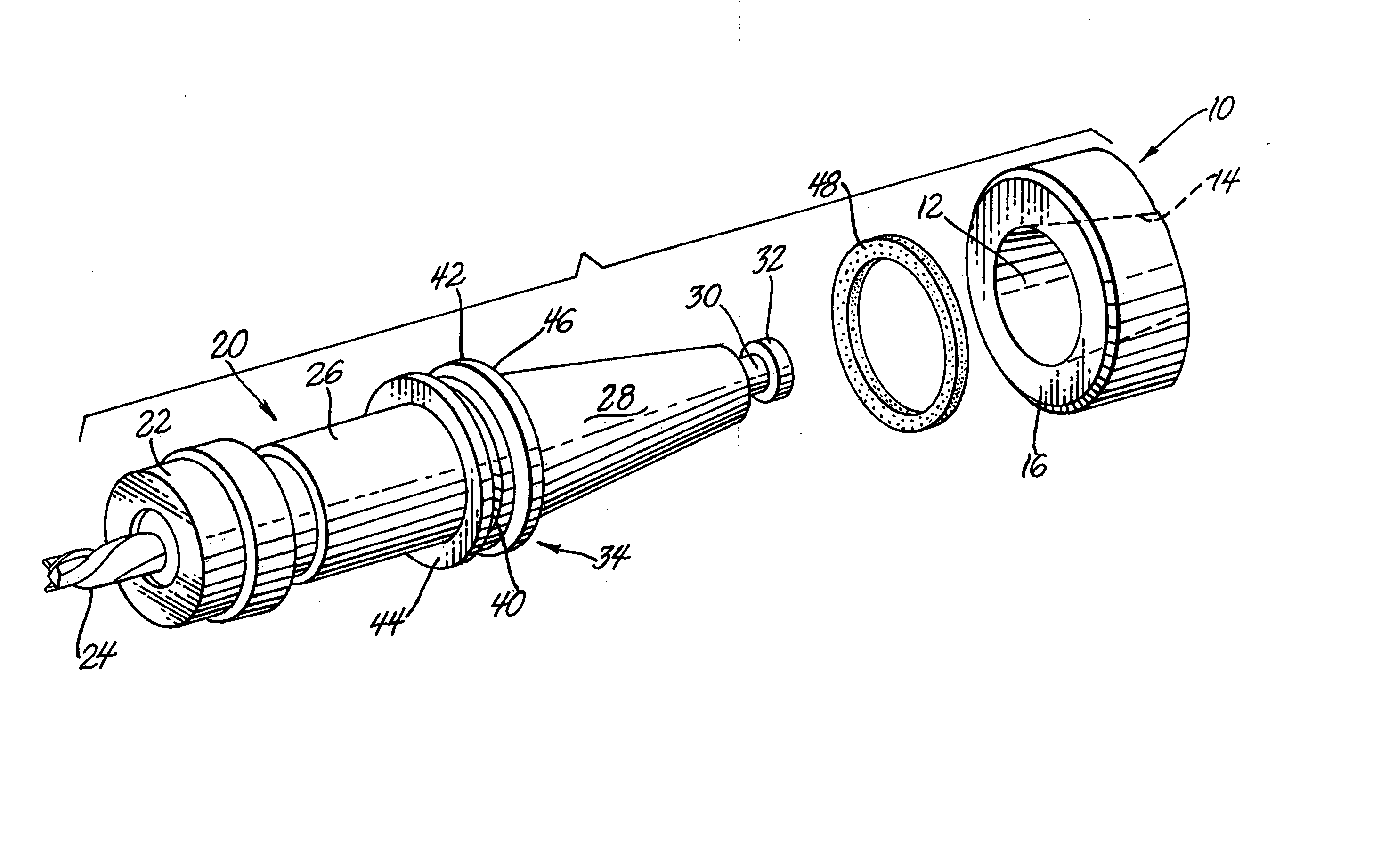
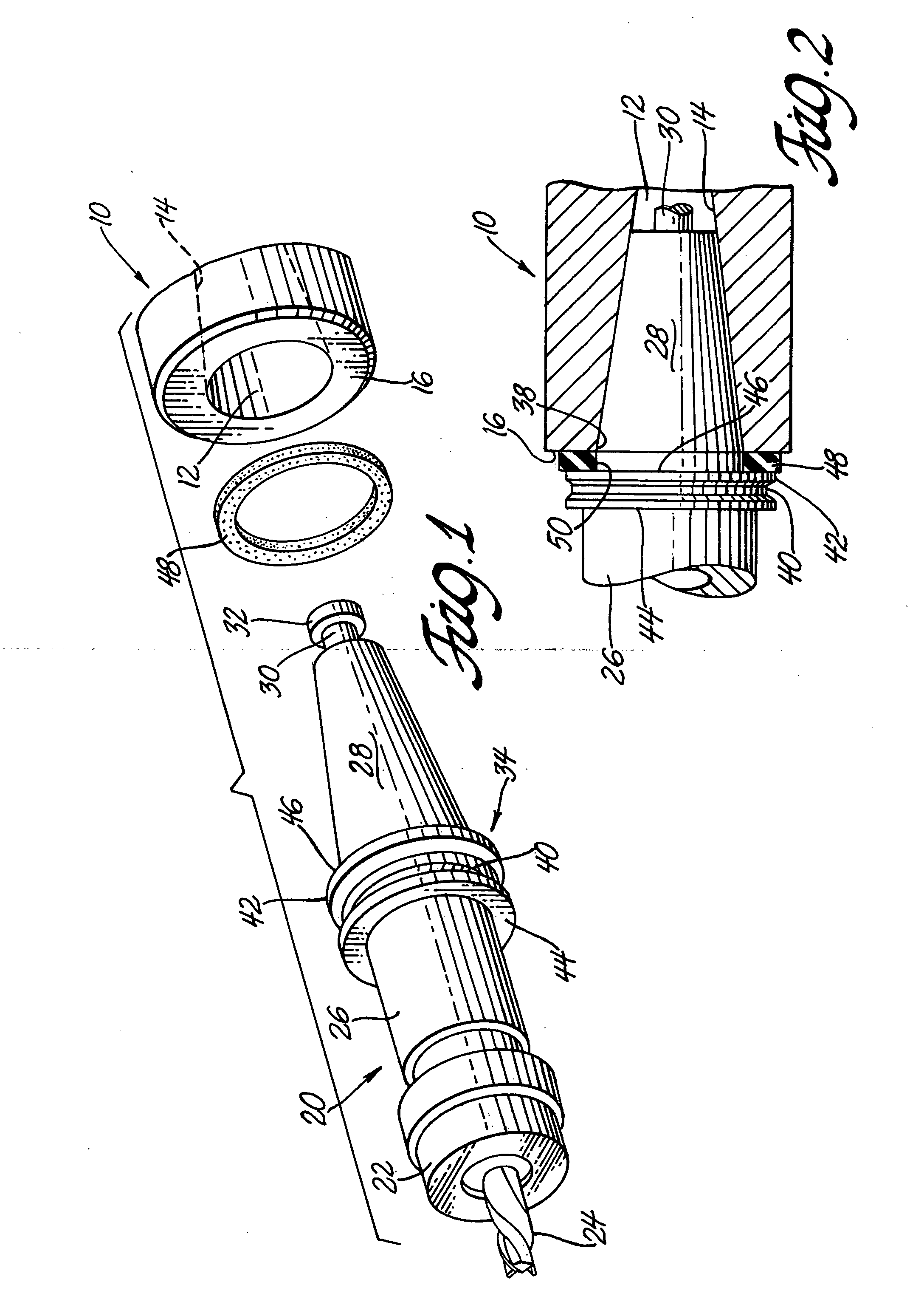
[0005] A ring of elastically deformable material is fitted on the circumference of the toolholder between the tool exchanger flange and the large diameter portion of its tapered shank. This ring serves as a compressible or deformable vibration dampening spacer between the flange on the circumference of the toolholder and the face of the spindle shaft of the machine tool. The thickness of the elastic spacer material fills the space between one side of the flange and the face of the spindle when the clamping mechanism of the machine tool pulls the tapered shank of the toolholder into the tapered socket of the spindle. When the toolholder is secured in the spindle by operation of the machine tool the elastic spacer is thus compressed, like a washer, to significantly dampen rotational vibrations arising during machining from imperfect fits between the tapered surfaces of the toolholder shank and the spindle socket.
[0006] The elastic spacer is made of a suitable material such as rubber or other relatively flexible polymer material. Matted or felted fibrous materials may also have suitable flexibility for spacer application. In the operation of the machine tool the spindle rotates and pushes the milling or boring tool against a machinable workpiece. The machining forces on the tool cause vibrations in the rotating combination of machine tool spindle, toolholder and tool. The fit of the toolholder shank into the spindle socket cannot be perfect and the rotation of the tool is eccentric with respect to the rotation of the spindle, and the tool bends, flexes and vibrates and chatters. This motion of the tool affects the dimensional accuracy of the machining operation. But the elastic spacer, compressed between the toolholder flange and the spindle face, markedly reduces the vibration and chatter of the tool. Chatter is a dynamic phenomenon that can appear in machining at any spindle speed as a result of self-excited vibration. The use of the low cost elastic spacer-damper provides great benefit to the accuracy of the machining operation.

Problems solved by technology

The machining forces on the tool cause vibrations in the rotating combination of machine tool spindle, toolholder and tool.
The fit of the toolholder shank into the spindle socket cannot be perfect and the rotation of the tool is eccentric with respect to the rotation of the spindle, and the tool bends, flexes and vibrates and chatters.
This motion of the tool affects the dimensional accuracy of the machining operation.

Method used


Image

  • Spacer adapter for toolholders
  • Spacer adapter for toolholders
  • Spacer adapter for toolholders

Examples


example

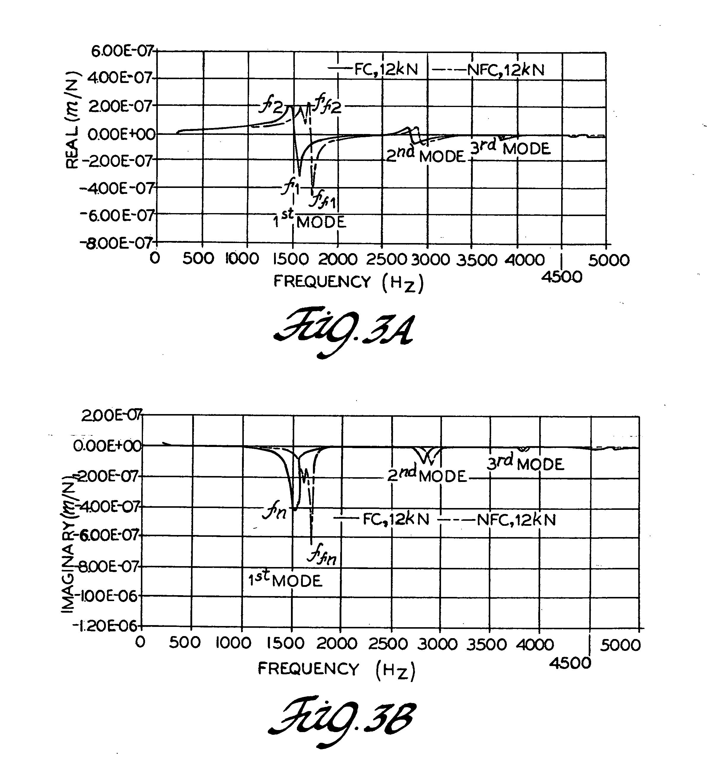
[0025] A CAT 40 toolholder with an end milling tool as depicted in FIG. 1 was subjected to dynamic tests and the frequency response function (FRF) of the toolholder-spindle system in the machine tool was measured. A CAT 40 toolholder is manufactured according to international specifications. In the example the 40 size tapered shank / spindle interface, the gage diameter of the spindle or toolholder taper (at the front or large end) is 44.450 mm and the taper length of the toolholder is 68.326 mm, the external diameter of the spindle is 88.90 mm, and the external diameter of the toolholder flange is 63.50 mm and the deviation accommodating clearance between the spindle face and the opposing end face of the toolholder flange is about 1 to 2 mm. For comparison purposes the standard tapered toolholder with and without the elastic damping spacer was tested. Elastic damping spacers used in tests described below were rings having an outside diameter of 62 mm, an inside diameter of 45 mm and ...


PUM

PropertyMeasurementUnit
Elasticityaaaaaaaaaa

Abstract

A toolholder for a cutting tool is disclosed for use with a machine tool having a main shaft or spindle with a flared or tapered end socket. The toolholder has a tool-holding end for a cutting tool and a tapered shank end for placement in the tapered socket of the machine tool spindle. The toolholder also has an annular flange near its tapered shank, the flange or collar generally being used for location and gripping by a tool exchange mechanism. An elastic spacer ring is used and compressed between said flange and the face of said machine tool shaft in machining operations for dampening vibrations and flexing of the toolholder and cutting tool.

Description

TECHNICAL FIELD [0001] This invention pertains to use of an elastic spacer between a toolholder and the face of a machine tool spindle. More specifically, this invention relates to the use of such a compressible spacer between the flange of a toolholder and a spindle to provide improved vibration damping and dynamic bending stiffness for milling and boring operations. BACKGROUND OF THE INVENTION [0002] Machine tools operated under computer numerical control (CNC) are widely used in manufacturing operations. For example, in automobile manufacturing they are used in milling and boring operations in making engine blocks and transmission cases. Machine tools are often used in machining centers and the tools may be designed for horizontal, vertical or multi-axis operation. A sophisticated machine tool provides the motive power and direction for the cutting operation and a suitable cutting tool provides means for shaping the metallic workpiece. A toolholder provides the interface between ...

Claims


Application Information

Patent Timeline
IPC IPC(8): B23B31/02B23C1/00
CPCB23B31/02B23B2250/16Y10T409/304312B23B31/006B23C2226/33
Inventor AGAPIOU, JOHN STILIANOSAAS, ROBERT K.
Owner GENERAL MOTORS COMPANY
Learn More