Ultrasonic micromixer with radiation perpendicular to mixing interface

a micromixer and ultrasonic technology, applied in microstructural devices, microstructures, microstructures, etc., can solve the problems of deteriorating ultrasonic waves, difficult miniaturization of devices used in bio-diagnosis fields, and unimportant channels of macro sizes, etc., to improve the mixing efficiency of sample fluids and facilitate the mixing of sample fluids.

Inactive Publication Date: 2005-09-29
KOREA INST OF MASCH & MATERIALS
View PDF19 Cites 8 Cited by
  • Summary
  • Abstract
  • Description
  • Claims
  • Application Information

AI Technical Summary

Benefits of technology

[0013] Therefore, if reliable operation is required, the active ultrasonic micromixer using the piezoelectric device is used in this field. The active ultrasonic micromixer is a device to enhance the mixing efficiency of the sample fluids using an outside energy source. The active ultrasonic micromixer radiates ultrasonic waves to cause the sample fluids to generate a turbulent flow in the chamber of the active ultrasonic micromixer, thus easily mixing the sample fluids. The active ultrasonic micromixer is insensitive to gas bubbles and is capable of controlling the mixing of the sample fluids according to the level of input energy.

Problems solved by technology

Therefore, issues which are unimportant in channels of macro sizes may arise.
As such, due to the long micro channels, the miniaturization of the devices used in the bio-diagnosis fields is very difficult.
However, because the radiation direction of the ultrasonic waves is parallel to the mixing interface between the two sample fluids, the effect of the ultrasonic waves is deteriorated.

Method used


Image

  • Ultrasonic micromixer with radiation perpendicular to mixing interface
  • Ultrasonic micromixer with radiation perpendicular to mixing interface
  • Ultrasonic micromixer with radiation perpendicular to mixing interface

Examples


Embodiment Construction

[0018] Hereinafter, a preferred embodiment of the present invention will be described in detail with reference to the attached drawings.

[0019] Reference now should be made to the drawings, in which the same reference numerals are used throughout the different drawings to designate the same or similar components.

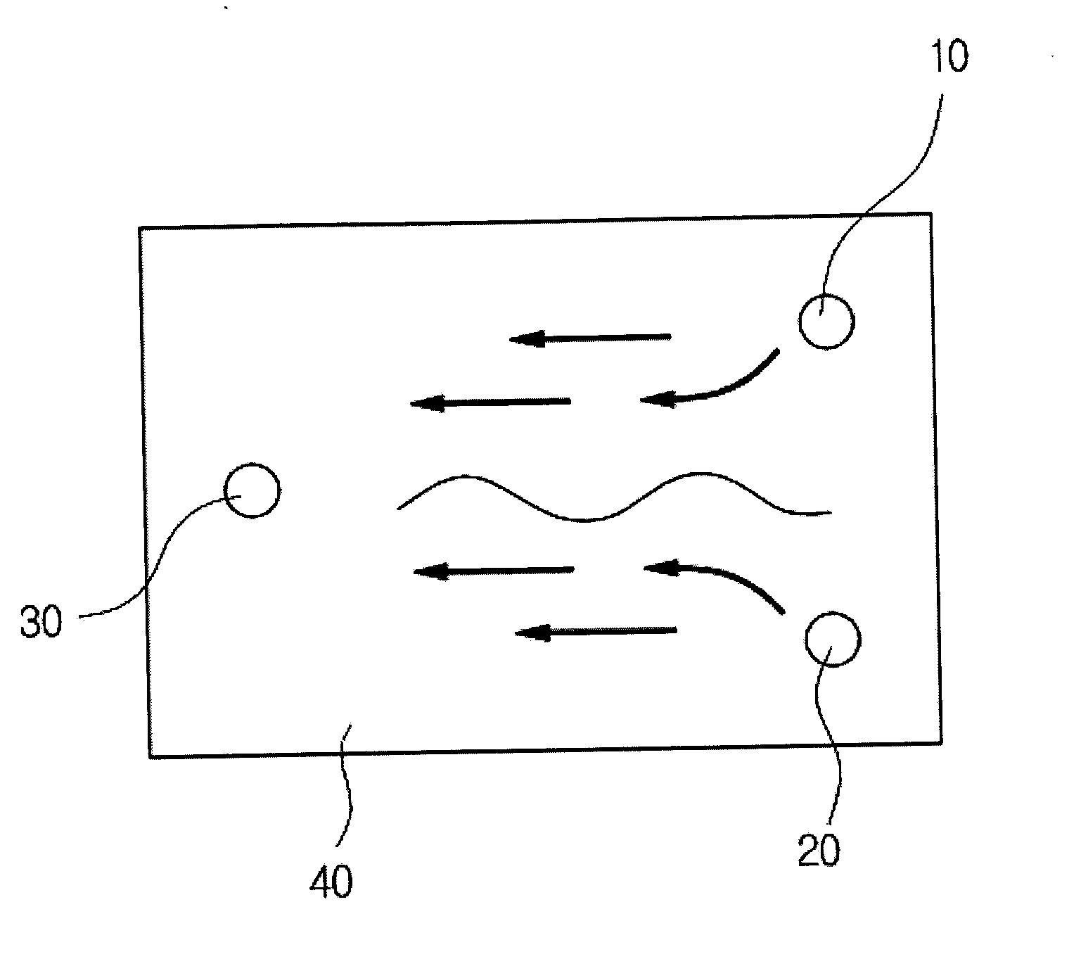
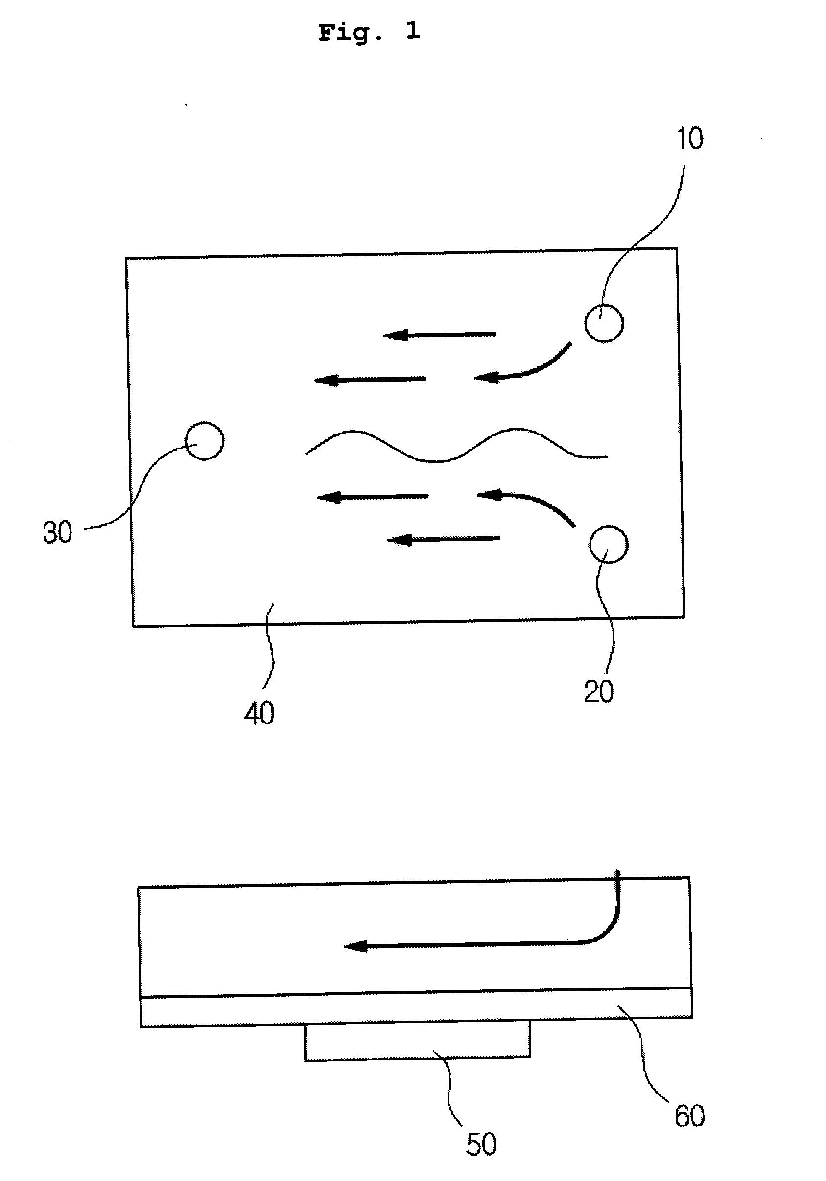
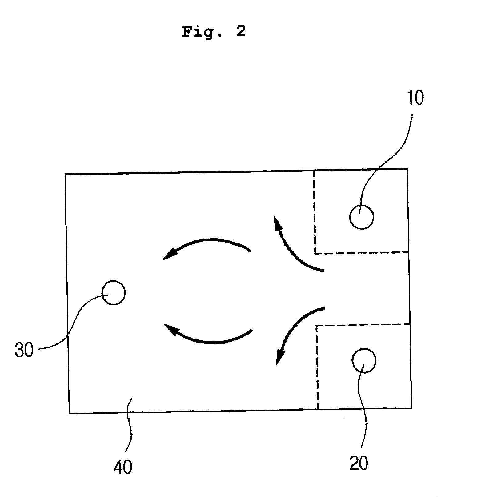
[0020]FIG. 2 is a plan view of an ultrasonic micromixer with radiation perpendicular to a mixing interface, in which first and second inlets 10 and 20 and an outlet 30 are provided on an upper surface of a chamber 40, according to a preferred embodiment of the present invention. FIG. 3 is a sectional view of the ultrasonic micromixer of FIG. 2 to show the first and second inlets 10 and 20, first and second guide channels 15 and 25 and a chamber 40.

[0021] Referring to FIGS. 2 and 3, the ultrasonic micromixer according to the preferred embodiment of the present invention mixes a plurality of sample fluids passing through micro channels. The ultrasonic micromixer includes the...


PUM

PropertyMeasurementUnit
heightsaaaaaaaaaa
specific weightaaaaaaaaaa
timeaaaaaaaaaa

Abstract

The present invention provides an ultrasonic micromixer which is used in fields of bio-MEMS (micro-electro-mechanical-system) and μ-TAS (total analysis system) and radiates ultrasonic waves using a piezoelectric device in a direction perpendicular to a horizontal mixing interface between a plurality of sample fluids flowing in a chamber, so as to accelerate the mixing of the sample fluids, thus producing an evenly mixed sample. The ultrasonic micromixer includes a plurality of independent inlets, and a plurality of guide channels which are coupled to the inlets at different heights. The ultrasonic micromixer further includes the chamber to allow the plurality of sample fluids, discharged from the guide channels, to mix with each other while flowing through the chamber, and an outlet to discharge the mixed sample fluids. The ultrasonic micromixer further includes a vibration plate which is attached to a lower portion of the chamber, and a piezoelectric device which is attached to a lower surface of the vibration plate to radiate ultrasonic waves in a vertical direction. Therefore, the ultrasonic micromixer achieves miniaturization, accuracy and integration of devices used in the fields of the bio-MEMS and μ-TAS.

Description

BACKGROUND OF THE INVENTION [0001] 1. Field of the Invention [0002] The present invention relates generally to ultrasonic micromixers which are used in fields of bio-MEMS (micro-electro-mechanical-system) and μ-TAS (total analysis system) to mix a plurality of sample fluids passing through micro channels, and more particularly, to an ultrasonic micromixer which provides a horizontal mixing interface between a plurality of sample fluids flowing in a chamber and radiates ultrasonic waves using a piezoelectric device in a direction perpendicular to the horizontal mixing interface between the sample fluids, thus enhancing the mixing efficiency of the sample fluids, thereby producing an evenly mixed sample. [0003] 2. Description of the Related Art [0004] Recently, bio-diagnosis techniques have been developed for miniaturization, accuracy and integration of devices used in the bio-diagnosis fields. Miniaturization of the devices provides several advantages, as follows: first, the amount o...

Claims


Application Information

Patent Timeline
Patent Type & Authority Applications(United States)
IPC IPC(8): B01F11/02B01F13/00B01L3/00B81B7/02C12M1/34G01N33/53G01N33/569
CPCB01F11/0266B01L3/5027B01F13/0059B01F31/86B01F33/30B81B7/02
Inventor HEO, PIL WOOKIM, DEOK JONGKIM, JAE YUNPARK, SANG JINYUN, EUI SOO
Owner KOREA INST OF MASCH & MATERIALS
Why Eureka
Try Eureka