
Radio transmission device, mutual authentication method and mutual authentication program

a mutual authentication and program technology, applied in the field of mutual authentication methods and mutual authentication programs, can solve problems such as the difficulty of applying conventional methods to radio home networks, and achieve the effect of simple structure and high concealability

Inactive Publication Date: 2005-09-29
SANYO ELECTRIC CO LTD
View PDF4 Cites 44 Cited by
  • Summary
  • Abstract
  • Description
  • Claims
  • Application Information

AI Technical Summary

Benefits of technology

[0025] An object of the invention is to provide a radio transmission device, a mutual authentication method and a mutual authentication program, which can perform mutual authentication with high concealability by a simple structure.
[0035] According to the above aspect of the invention, it is possible to prevent misidentification and electrical interference due to another home or office in the mutual authentication operation by a simple structure, and high security can be ensured in the radio transmission system.
[0036] Further, various remote control signal waveforms can be used as the authentication codes so that each user can store the authentication code required for the mutual authentication only by depressing one key on the remote control. Therefore, the configuration can be further simplified while ensuring the security in the mutual authentication.

Problems solved by technology

However, each device must perform complicated and sophisticated processing in a complicated encryption method, and this makes it difficult to apply the conventional method to radio home networks, which can be expected to come rapidly into widespread use.

Method used


Image

  • Radio transmission device, mutual authentication method and mutual authentication program
  • Radio transmission device, mutual authentication method and mutual authentication program
  • Radio transmission device, mutual authentication method and mutual authentication program

Examples


first embodiment

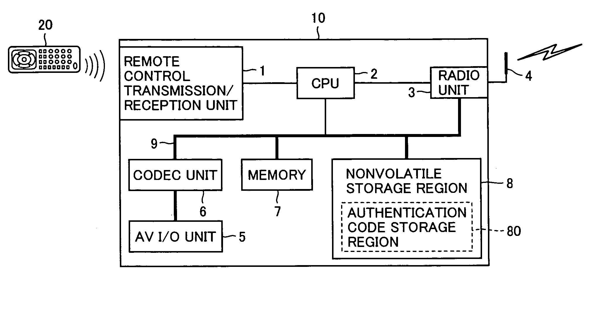
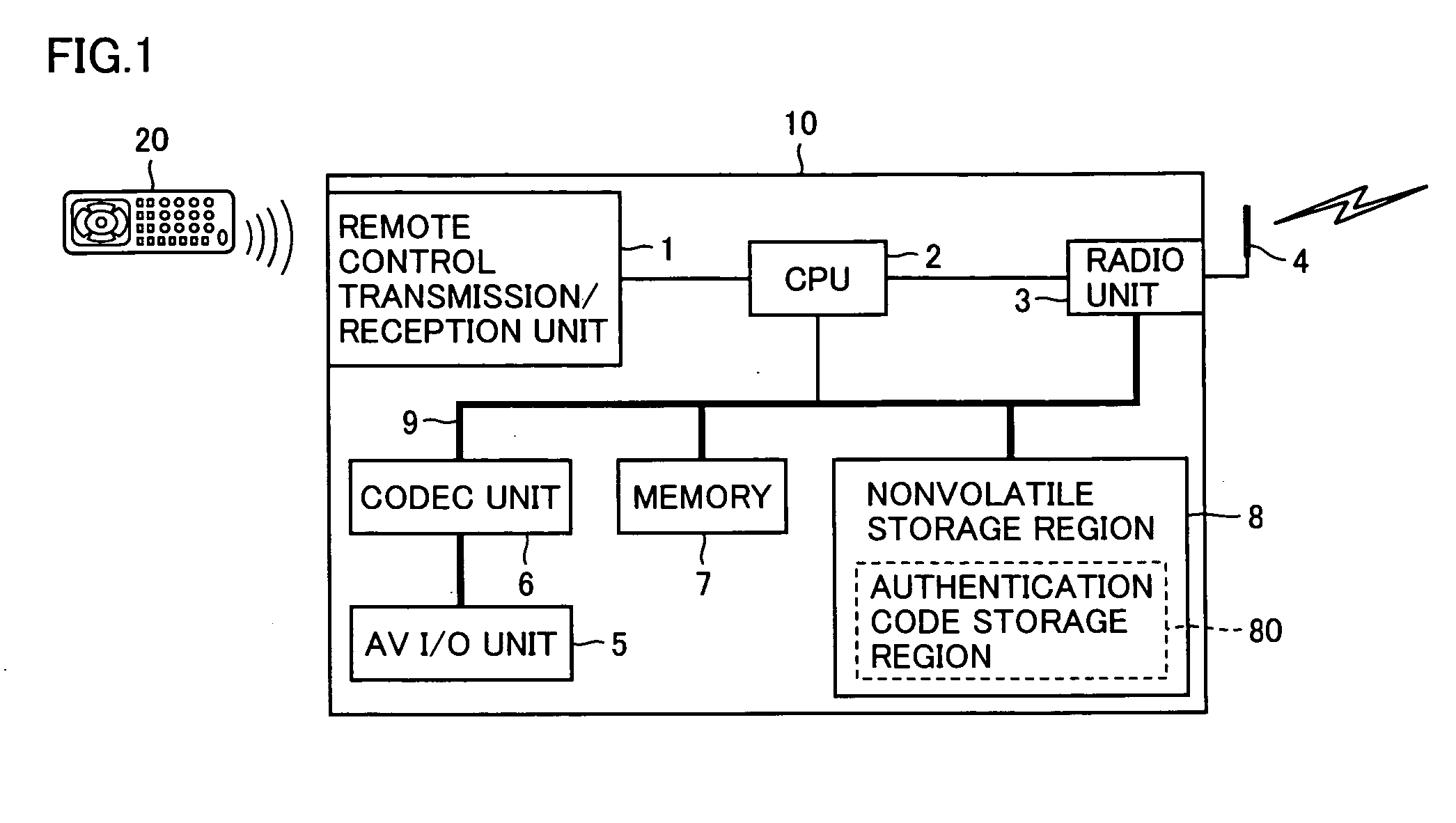
[0053]FIG. 1 is a functional block diagram illustrating a whole structure of a radio transmission device according to an embodiment of the invention. A radio transmission device transmitting AV data will now be described as an example of the radio transmission device in this embodiment.

[0054] Referring to FIG. 1, a radio transmission device 10 includes a remote control transmission / reception unit 1 for transmitting and receiving an infrared signal to and from a user's or another radio transmission device 10, and a CPU 2 controlling the whole device according to control information included in an electric signal, which is obtained by converting the received infrared signal, as well as a radio unit 3 and an antenna 4 for transmitting and receiving a radio signal to and from a radio transmission device (not shown) of an opposite party or side of the radio transmission.

[0055] Radio transmission device 10 further includes an AV input / output unit 5 for input / output of AV data, a codec u...

second embodiment

[0103] In the foregoing embodiment, the authentication code shared by radio transmission devices 10 performing the radio transmission is designated and recorded by the user entering the arbitrary character string via remote control 20 in the authentication code record mode. In this operation, the infrared signal of the authentication code emitted from remote control 20 is converted to the electric signal by remote control receiving unit 12 in remote control transmission / reception unit 1 in FIG. 1, and the authentication code is obtained by decoding the electric signal thus obtained, and is transferred to authentication code record region 80.

[0104] The electric signal, which is produced by remote control receiving unit 12, and will be referred to as a “remote control signal” hereinafter, is formed of a pulse signal string. Remote control receiving unit 12 samples the level of the remote control signal with a period of a fraction of a minimum pulse width, and extracts a remote contro...

third embodiment

[0118] According to the invention, the radio transmission device can perform the radio transmission of the data signal with high security by performing the mutual authentication already described in connection with the first and second embodiments. The data signal, which is transmitted by radio, may include a program signal for controlling a home electric appliance or a computer connected to the radio transmission device, in addition to the AV data already described. Third to fifth embodiments will now be described in connection with forms of use of the radio transmission device of the invention in the radio transmission systems.

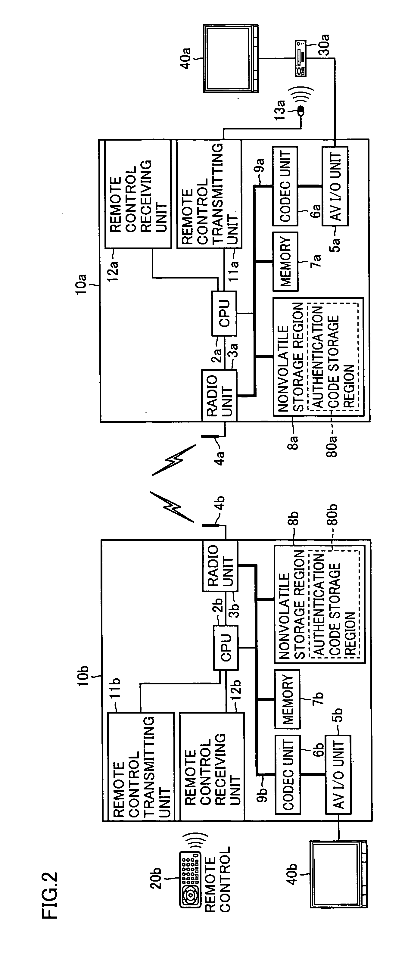
[0119]FIG. 10 schematically illustrates another example of a manner of use of a radio transmission device according to the invention.

[0120] Referring to FIG. 10, AV data display device 40a (e.g., television set) and AV data reproducing device 30a (e.g., DVD player) connected to AV data display device 40a are arranged in the home. In a room of the home, an ...


PUM


Abstract

A user operates a remote control to enter an authentication code shared by a plurality of radio transmission devices performing radio transmission. Remote control transmission / reception unit 1 converts an infrared signal received from the remote control to an electric signal, and extracts the authentication code from the electric signal. The authentication code is recorded on an authentication code record region in a nonvolatile storage region. In an authentication communication mode, a radio unit encrypts a radio unit MAC address with the authentication code used as a key, and transmits it. Further, the radio unit decrypts the radio unit MAC address returned from the radio transmission device of the opposite party of the transmission with the authentication code used as the key. The radio transmission device obtains the radio unit MAC address of the opposite party of the transmission, and ends the authentication mode.

Description

BACKGROUND OF THE INVENTION [0001] 1. Field of the Invention [0002] The present invention relates to a radio transmission device, a mutual authentication method and a mutual authentication program, and more particularly to a radio transmission device performing mutual authentication when performing radio transmission of data signals as well as a mutual authentication method and a mutual authentication program executed by such a radio transmission device. [0003] 2. Description of the Background Art [0004] In recent years, large attention has been given to a field of home networks, and technologies for establishing radio home networks have been actively developed. As an example of such technologies, there has been developed a radio transmission device, which couples a home-use electric appliance and a computer by radio in a space of a limited area such as a home or office. For example, there has been developed a radio transmission device, which couples by radio an AV data reproducing ...

Claims


Application Information

Patent Timeline
IPC IPC(8): H04L9/00G09C1/00H04L9/32H04L12/28
CPCG08C2201/40H04L2209/80H04L9/3273
Inventor KITA, YOSHIKAZUMIHARA, YOSHIKAZU
Owner SANYO ELECTRIC CO LTD
Learn More