Heat shielded air intake system

a heat shielded air and intake system technology, applied in the direction of charge feed system, air cleaner for fuel, fuel additives, etc., can solve the problems of affecting the efficiency of the engine, and affecting the performance of the engin

Inactive Publication Date: 2005-10-06
ADVANCED FLOW ENG
View PDF21 Cites 61 Cited by
  • Summary
  • Abstract
  • Description
  • Claims
  • Application Information

AI Technical Summary

Benefits of technology

[0015] In still a further aspect of the present invention, an air filter system includes a housing having a rear panel and a side panel. The rear panel and the side panel each have a top edge formed to interface to the hood of a vehicle so that the housing incorporates the vehicle hood to provide thermal isolation of intake air from engine compartment heat. The air filter system also includes an air intake tube connected to a stock air intake tract. The housing has a diagonal panel that the air intake tube is attached to and passes through, and the diagonal panel is disposed at an angle that provides positioning of the air intake tube, which is mounted to the diagonal panel, so that an effluent end of the air intake tube matches a stock location of a stock air intake tract. A washable, reusable air filter is connected to and supported by the air intake tube so that the intake air is filtered through the air filter and passes through the air intake tube into the stock air intake tract.

Problems solved by technology

The features and filter design choices that lead to improvements in one of these parameters (e.g., particle entrapment, airflow permeability, and filter lifetime) can lead to declines in the other performance parameters.
Impeded airflow tends to decrease engine efficiency, horsepower, torque, and fuel economy.
The stock air filter is typically a non-reusable unit having a relatively short expected filter lifetime that requires the stock filter to be replaced periodically.

Method used


Image

  • Heat shielded air intake system
  • Heat shielded air intake system
  • Heat shielded air intake system

Examples


Embodiment Construction

[0028] The following detailed description is of the best currently contemplated modes of carrying out the invention. The description is not to be taken in a limiting sense, but is made merely for the purpose of illustrating the general principles of the invention, since the scope of the invention is best defined by the appended claims.

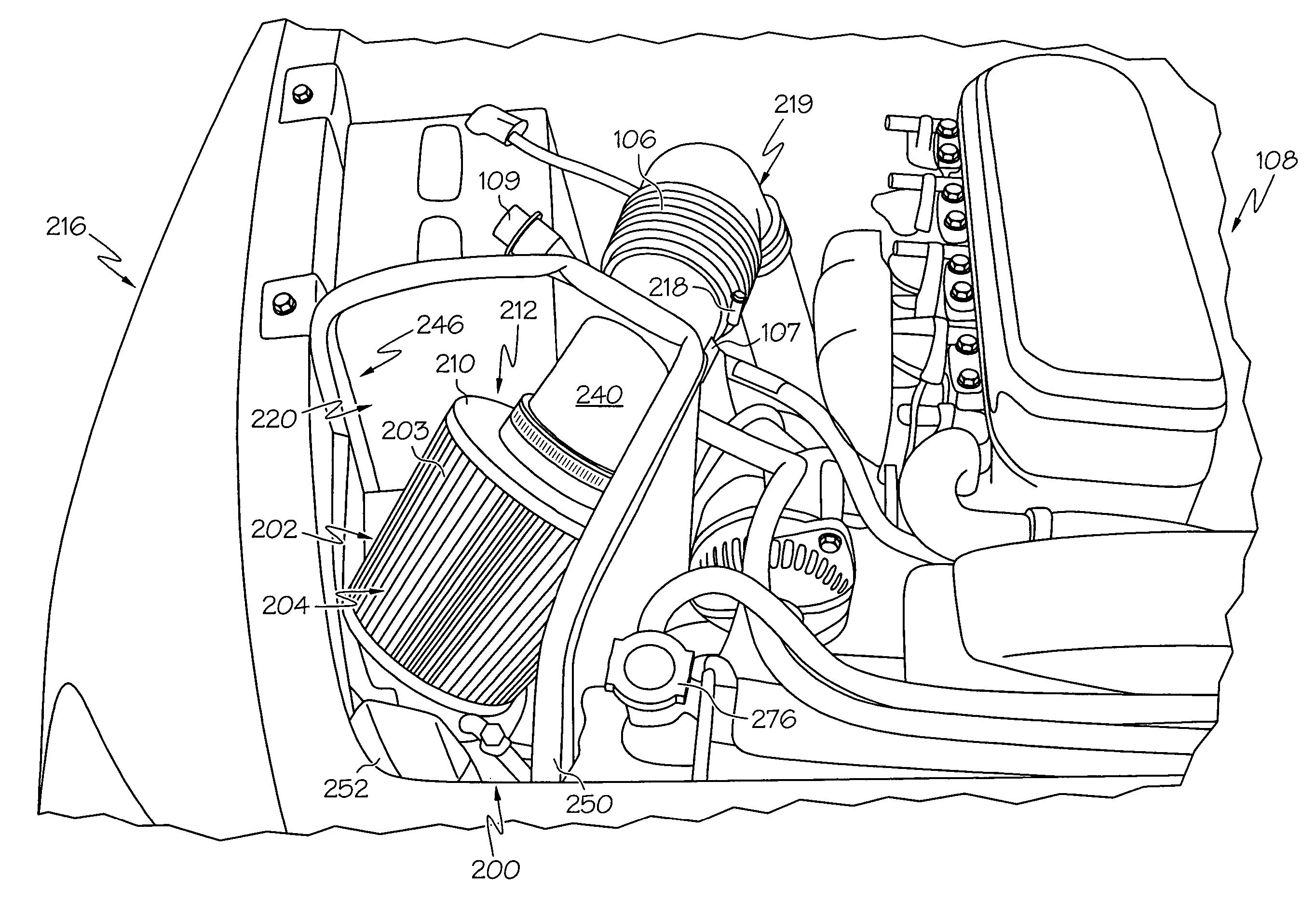
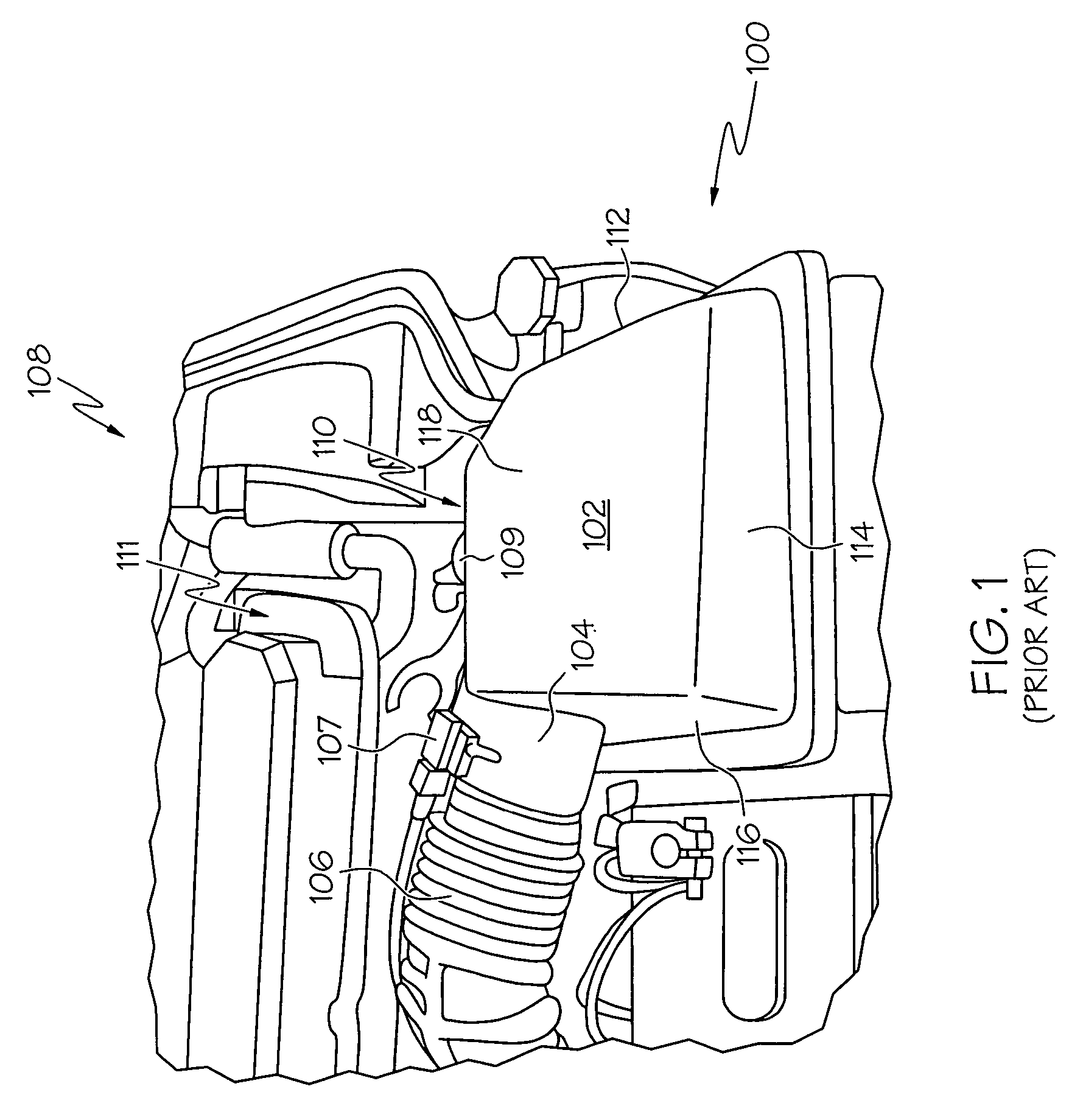
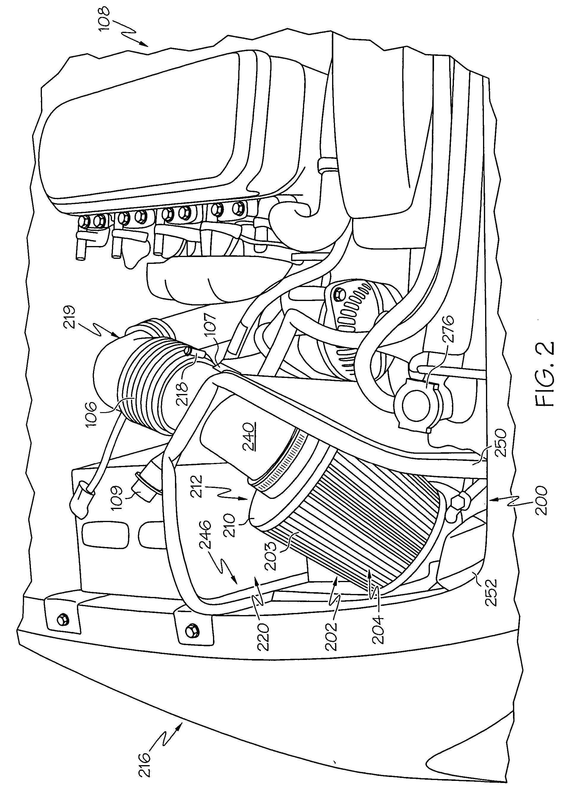
[0029] Broadly, the present invention provides air intake and filtering for an internal combustion engine, such as found in automotive vehicles and, in particular, 2003 and later model years for Dodge Cummins trucks with a 5.9 Liter (L) turbo diesel engine. An embodiment of the present invention may be used to replace the existing, i.e., stock, or original equipment manufacturer (OEM), air filter and air box with a washable, reusable air filter, heat shield housing to protect the air filter from engine heat, and air intake tube connecting to the existing stock air intake tract that allow more airflow into the engine and isolate the reusable filter and...


PUM


Abstract

An air filter system includes a housing having, for example, a rear panel and a side panel, each having a top edge formed to interface to the hood of a vehicle so that the housing incorporates the vehicle hood to provide thermal isolation of intake air from engine compartment heat. The air filter system connects to a stock air intake tract through an air intake tube. The housing has a diagonal panel that the air intake tube is attached to and passes through. The diagonal panel is disposed at an angle that provides positioning of the air intake tube so that an effluent end of the air intake tube matches the stock location of the stock air intake tract. A washable, reusable air filter supported by the air intake tube filters the intake air and passes it through the air intake tube into the stock air intake tract.

Description

CROSS-REFERENCE TO RELATED APPLICATIONS [0001] This application claims the benefit of U.S. Provisional Patent Application No. 60 / 559,710, filed on Apr. 5, 2004.BACKGROUND OF THE INVENTION [0002] This invention relates to high performance air intake systems and, in particular, to a high flow air intake system that filters the intake air, such as for use within the 2003 and later model years for Dodge Cummins trucks with a 5.9 Liter turbo diesel engine. [0003] It is well known that efficiency for a thermodynamic system—such as an automobile engine—increases proportionally with the difference in temperature between the system's input and its output. In the case of an automobile engine, for example, the difference between the input and output temperatures can be increased by protecting the intake air from heat, keeping it cooler. At the same time, the intake air for an internal combustion engine usually needs to be filtered without restricting the flow (measured as volume of gas per uni...

Claims


Application Information

Patent Timeline
Patent Type & Authority Applications(United States)
IPC IPC(8): F02M35/02F02M35/04F02M35/10
CPCF02M35/04F02M35/0203
Inventor NIAKEN, SHAHRIAR NICKZAMBRANO, SAUL DANIELBARRON, CHRISTOPHER M.
Owner ADVANCED FLOW ENG
Why Eureka
Try Eureka