Solenoid valve

a solenoid valve and valve body technology, applied in the direction of valve operating means/release devices, pressure relieving devices on sealing faces, transportation and packaging, etc., can solve the problems of stator core magnetization, plugging and locking, magnetic reluctance in the magnetic circuit,

Inactive Publication Date: 2005-10-06
JTEKT CORP
View PDF3 Cites 32 Cited by
  • Summary
  • Abstract
  • Description
  • Claims
  • Application Information

AI Technical Summary

Benefits of technology

[0008] In view of the foregoing, it is an object of the present invention to provide an improved solenoid valve. In order to achieve the above and other objects, an aspect of the present invention provides a solenoid valve comprising a solenoid portion and a valve portion. The solenoid portion is constructed by a stator core, an electromagnetic coil and a plunger. The valve portion is constructed by a valve sleeve and a spool axially forming plural lands in series. The plunger is axially moved by electromagnetic attraction and drives the spool. The pressurized areas of the plunger and the land of the spool closest to the plunger have the same areas. Therefore, the volume in an intermediate space between the plunger and the spool is constant and contaminants in the oil are not sucked into the intermediate space.

Problems solved by technology

In the prior art, since the plunger slides in the bore, the contaminants may become lodged between the bore and the plunger, whereby the plunger may lock.
However, the wider gap increases the magnetic reluctance in the magnetic circuit, which reduces magnetization of the stator core and the slide.
Therefore the magnetic attraction force to the plunger is reduced and the valve characteristics become unstable, or the electromagnetic coil must become larger to obtain suitable valve characteristics.
In the second prior art, however, the diaphragm requires a rubber material which has oil resistance and soft elasticity even in a high / low temperature environment, whereby its product costs are higher.

Method used


Image

  • Solenoid valve
  • Solenoid valve
  • Solenoid valve

Examples


first embodiment

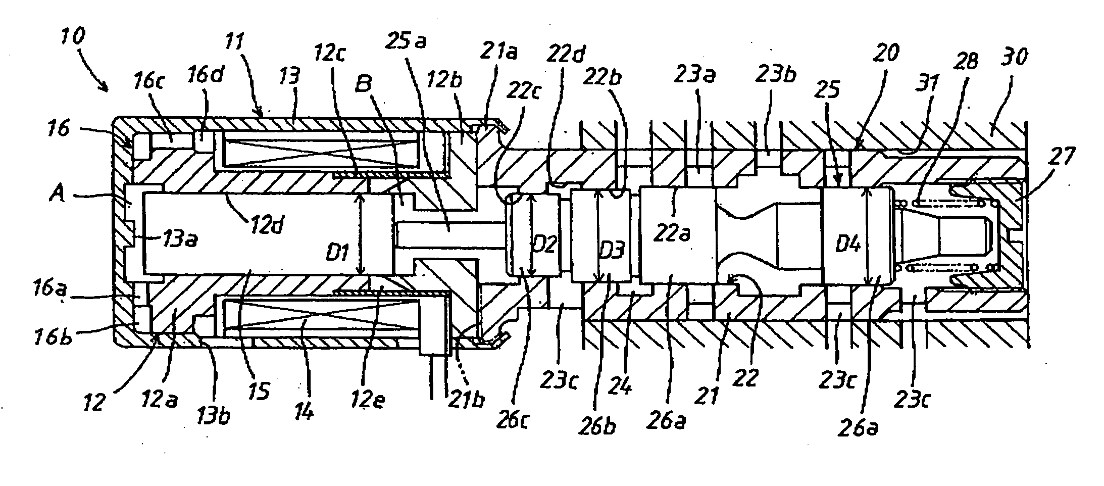
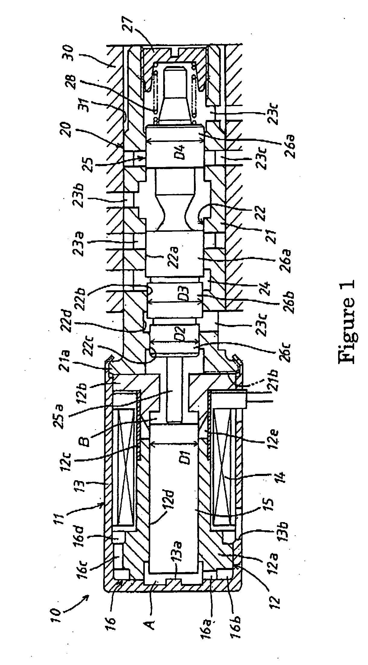
[0024] As shown in FIG. 1, in the solenoid valve of the first embodiment, the valve sleeve 21 is fixed in the valve body 30 with liquid tightness. Instead of the valve sleeve 21, the valve bore 22 and the ports 23a-23c may be formed in the valve body 30 itself.

[0025] During rest of the solenoid valve while the electromagnetic coil 14 is not energized, the spring 28 forces the plunger 15 and the spool 25 to contact each other and to set the plunger 15 on the central projection 13a of the inner bottom of the cover 13 as the retracted end position. This fully opens the opening between the supply port 23a and the control port 23b, and closes the opening between the control port 23b and the drain port 23c. In this situation, an amount of oil supplied from a pump, not shown, to a hydraulic equipment such as a clutch piston to be controlled, not shown, is supplied via the supply port 23a and the control port 23b. When the electromagnetic coil 14 is energized, the stator core 12 is magnetiz...

second embodiment

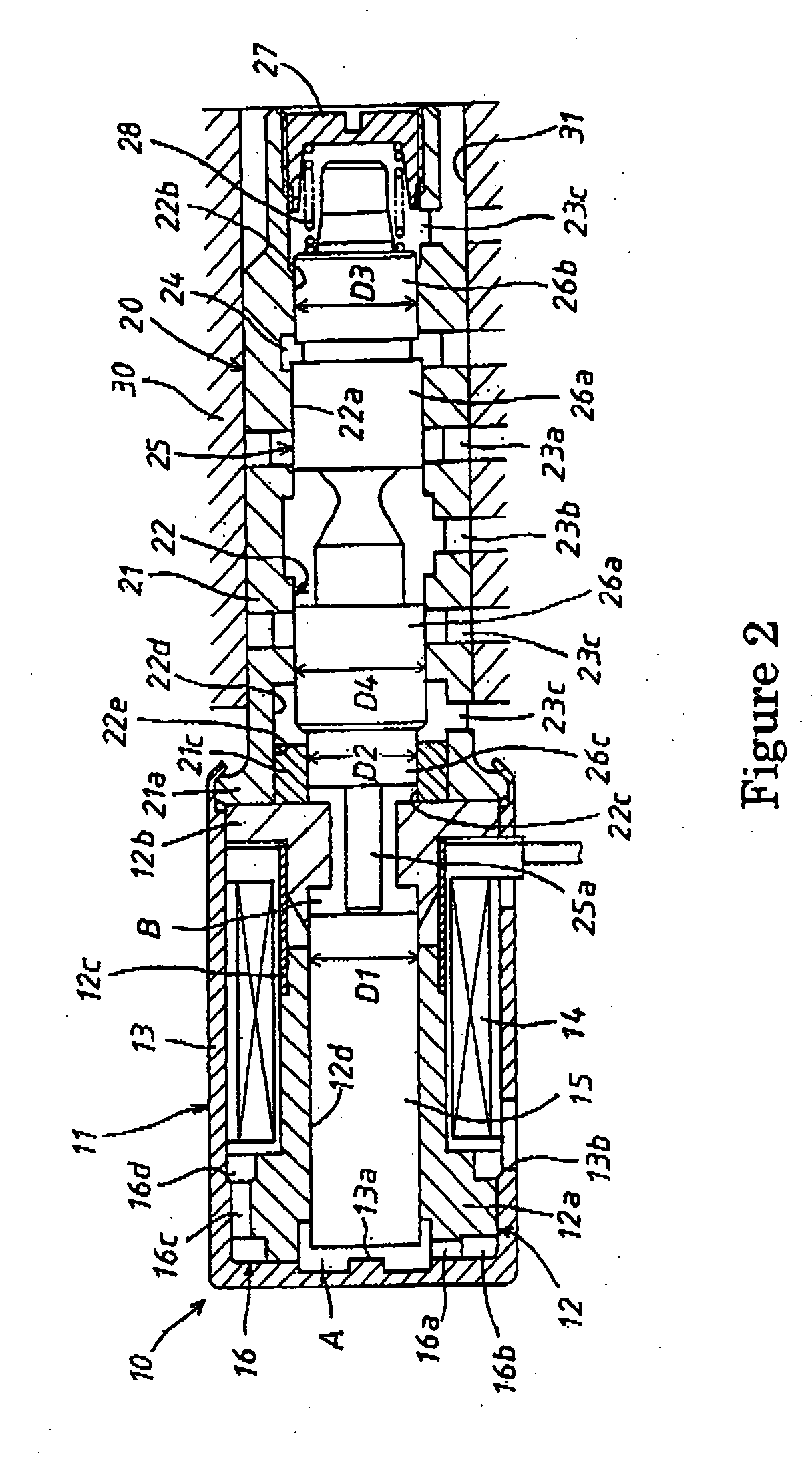
[0032] In the second embodiment, when the solenoid is inactive, the opening between the supply and the control ports 23a and 23b is closed, but the opening between the control and the drain ports 23b and 23c is fully opened, whereby the oil from the pump is not supplied to the hydraulic equipment but is instead drained through the drain port 23c. When the solenoid becomes active, the openings between the supply and the control ports 23a and 23b, and between the control and the drain ports 23b and 23c, are controlled according to the current flowing through the coil 14, and the oil from the pump is supplied to the hydraulic equipment through the control port 23b.

[0033] In the second embodiment, as in the first embodiment, the pressurized area of the plunger 15 is as large as the third land 26c of the spool 25, namely the diameters D1 and D2 are the same, so that the volume in the intermediate space B does not change even if the plunger 15 and the spool 25 move together. Therefore, e...

third embodiment

[0044] In the third embodiment, since the diameter D1 of the plunger 15 is the same as the diameter D3 of the second land 26b, the volume in the intermediate space B formed between each end of the plunger 15 and the second land 26b does not change, whereby the oil including the contaminants is not sucked into the intermediate space B. Therefore, even without a diaphragm or similar element the plunger 15 is prevented from locking due to contaminants lodged between the plunger 15 and the central bore 12d.

[0045] The volume in the tip space A formed between the bottom of the cover 13 and the end surface of the plunger 15 changes according to the slide of the plunger 15. However, since the tip space A connects to the outside via the aperture 13e of the cover 13 and the labyrinth inlet / outlet passage 18, the contaminants in the oil hardly reach the tip space A and most of them are eliminated during the opposite movement of the plunger 15. Iron powder is the contaminant which mainly makes...


PUM


Abstract

A solenoid valve comprises a solenoid portion 10 and a valve portion 20. The solenoid portion 10 is constructed by a stator core 12, an electromagnetic coil 14 and a plunger 15. The valve portion 20 is constructed by a valve sleeve 21 and a spool 25 axially forming plural lands 26a-26c in series. The plunger 15 is axially moved by electromagnetic attraction and drives the spool 25. There are formed the same pressurized areas at the plunger 15 and the land of the spool 25 closest to the plunger 15. Therefore, the volume in an intermediate space B between the plunger 15 and the spool 25 is constant and contaminants in the oil are not sucked into the intermediate space B.

Description

INCORPORATION BY REFERENCE [0001] The present application claims priority under 35 U.S.C. § 119 to Japanese Patent Application No. 2004-099094, filed on Mar. 30, 2004. The contents of that application are incorporated herein by reference in their entirety. BACKGROUND OF THE INVENTION [0002] 1. Field of the Invention [0003] This invention relates to a solenoid valve whose sliding plunger makes a valve spool move. [0004] 2. Discussion of the Background [0005] A conventional solenoid valve may be installed into an electronically controlled automatic transmission. The solenoid valve is inserted into a valve body formed in an oil pan of the automatic transmission. Japanese patent laid open 01-242884 is prior art disclosing such a solenoid valve. The prior art solenoid valve includes a solenoid portion and a valve portion. In the solenoid portion, there is a stator core which is coaxially constructed by a core and a yoke in series. A bore is formed at the axial center of the stator core, ...

Claims


Application Information

Patent Timeline
Patent Type & Authority Applications(United States)
IPC IPC(8): F16K11/07F16K31/06F16K39/04
CPCF16K11/0708F16K39/04F16K31/0613Y10T137/86622
Inventor SEGI, MASAYASUZUKI, MIKIOSUZUKI, MASARU
Owner JTEKT CORP
Why Eureka
Try Eureka