Aluminum bonding member and method for producing same

a technology of aluminum bonding and aluminum foil, which is applied in the direction of laminated elements, basic electric elements, light and heating apparatus, etc., can solve the problems of difficult to stabilize the performance of radiating fins, deterioration of heat sink characteristics, and difficulty in ensuring the stability of radiating fins, etc., to achieve simple and inexpensive production of aluminum bonding members and high cooling power

Inactive Publication Date: 2005-10-06
DOWA METALTECH CO LTD
View PDF33 Cites 22 Cited by
  • Summary
  • Abstract
  • Description
  • Claims
  • Application Information

AI Technical Summary

Benefits of technology

[0017] According to the present invention, it is possible to simply and inexpensively produce an aluminum bonding member capable of being used as a cooling member having a high cooling power.

Problems solved by technology

However, in the conventional method for soldering a ceramic substrate on a metal base plate, heat sink characteristics are deteriorated by the solder, and the thermal conductivity of the radiating grease used for mounting the radiating fin on the metal base plate or the like is a few W / mK which is extremely small, so that there is a problem in that the heat sink characteristics are further deteriorated.
In addition, there are some cases where the yield of products may be deteriorated by solder voids.
In the method disclosed in Japanese Patent Laid-Open No. 4-363052, since an air cooling radiating fin is used, the cooling power of the radiating fin is generally lower than that of a water cooling system, so that there is a problem in that it is difficult to stabilize the performance of the radiating fin.
Therefore, costs for the die and producing apparatus are relatively high, and there are some cases where it is difficult to enhance the uniformity and working precision of the preform substrates.
Moreover, since the porosity of the preform substrates is not less than 5% and is less than 50%, there are some cases where it is difficult to fill a molten metal in the preform substrates to mechanically realize the bonding by the anchor effect.

Method used


Image

  • Aluminum bonding member and method for producing same
  • Aluminum bonding member and method for producing same
  • Aluminum bonding member and method for producing same

Examples


first preferred embodiment

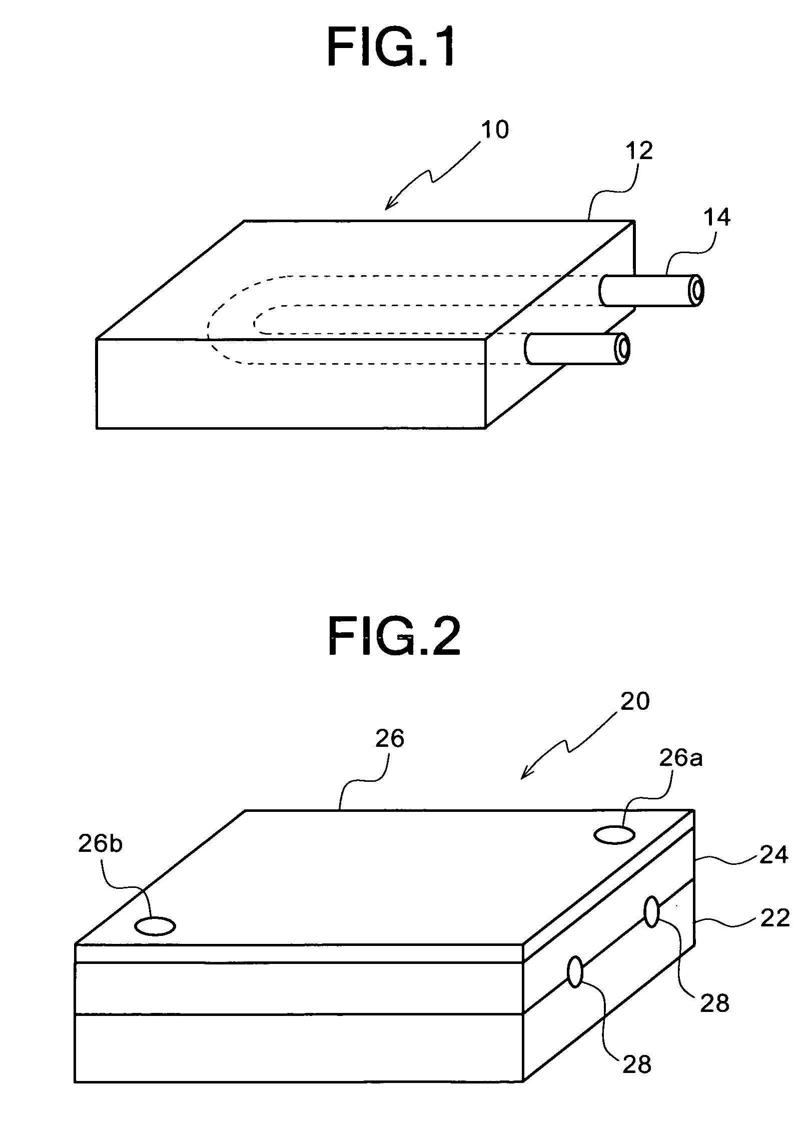
[0033] Referring to FIGS. 1 through 3, the first preferred embodiment of an aluminum bonding member and a method for producing the same according to the present invention will be described below.

[0034] As shown in FIG. 1, an aluminum bonding member 10 in this preferred embodiment comprises an aluminum member 12 having a substantially rectangular planar shape, and a substantially U-shaped tubular member 14 having a substantially annular sectional shape. Both of the opening end portions of the tubular member 14 protrude from the aluminum member 12 to be open to the outside. A portion of the tubular member 14 between the opening end portions is arranged in the aluminum member 12 to contact the aluminum member 12 to be bonded directly thereto. As an example of the tubular member 14, a stainless pipe having a diameter of about 10 mm may be used. Alternatively, a pipe of a metal, such as molybdenum (Mo) or copper (Cu), or a pipe of a ceramic, such as alumina or zirconia, may be used if i...

second preferred embodiment

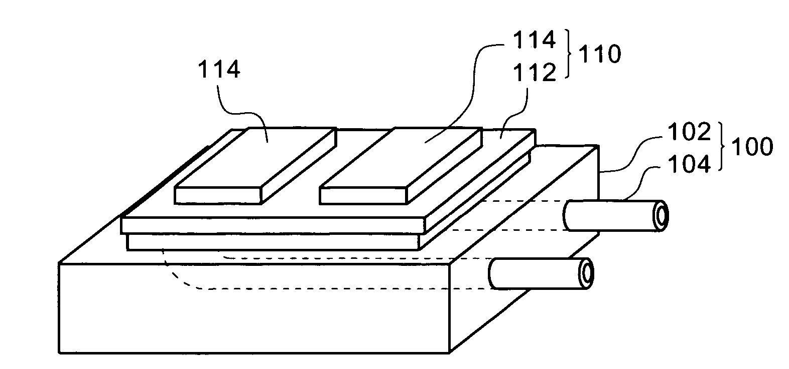
[0045] Referring to FIGS. 4 through 6, as the second preferred embodiment of an aluminum bonding member and a method for producing the same according to the present invention, an embodiment wherein the same aluminum bonding member as the aluminum bonding member 10 in the first preferred embodiment is bonded directly to a copper / ceramic circuit board will be described below.

[0046] As shown in FIG. 4, similar to the first preferred embodiment, an aluminum bonding member 100 in this preferred embodiment comprises an aluminum member 102 having a substantially rectangular planar shape, and a substantially U-shaped tubular member 104 having a substantially annular sectional shape. Both of the opening end portions of the tubular member 104 protrude from the aluminum member 102 to be open to the outside. A portion of the tubular member 104 between the opening end portions is arranged in the aluminum member 102 to contact the aluminum member 102 to be bonded directly thereto.

[0047] The alu...

third preferred embodiment

[0061] Referring to FIGS. 7 through 10, as the third preferred embodiment of an aluminum bonding member and a method for producing the same according to the present invention, an embodiment wherein the same aluminum bonding member as the aluminum bonding member 10 in the first preferred embodiment is bonded directly to an aluminum / ceramic circuit board will be described below.

[0062] As shown in FIG. 7, similar to the first preferred embodiment, an aluminum bonding member 200 in this preferred embodiment comprises an aluminum member 202 having a substantially rectangular planar shape, and a substantially U-shaped tubular member 204 having a substantially annular sectional shape. Both of the opening end portions of the tubular member 204 protrude from the aluminum member 202 to be open to the outside. A portion of the tubular member 204 between the opening end portions is arranged in the aluminum member 202 to contact the aluminum member 202 to be bonded directly thereto.

[0063] The ...


PUM

PropertyMeasurementUnit
porosityaaaaaaaaaa
porosityaaaaaaaaaa
diameteraaaaaaaaaa

Abstract

There is provided an aluminum bonding member capable of being simply and inexpensively produced and capable of being used as a cooling member having a high cooling power. The aluminum bonding member 10 has an aluminum member 12 of aluminum or an aluminum alloy exposed to the outside, and a tubular member 14 of a material which does not melt at a temperature close to the melting point of aluminum or the aluminum alloy. Both of the opening end portions of the tubular member 14 are open to the outside of the aluminum member 12. A portion of the tubular member 14 between the opening end portions extends in the aluminum member 12, and the outer peripheral surface of the portion of the tubular member 14 extending in the aluminum member 12 is bonded directly to the aluminum member 12.

Description

BACKGROUND OF THE INVENTION [0001] 1. Field of the Invention [0002] The present invention generally relates to an aluminum bonding member and a method for producing the same. More specifically, the invention relates to an aluminum bonding member, in which a tubular member for allowing the flow of a cooling agent and which is used as a cooling member for electronic parts, such as metal / ceramic circuit boards, and a method for producing the same. [0003] 2. Description of the Prior Art [0004] As a conventional method for mounting a cooling member, such as a radiating fin, on a metal / ceramic circuit board wherein a metal circuit plate is bonded to one side of a ceramic substrate and a radiating metal plate is bonded to the other side thereof, there is known a method for soldering one or a plurality of ceramic substrates, to each of which a metal circuit plate having a semiconductor chip soldered thereon is bonded, on a metal base plate (a radiating plate) or a composite material and for...

Claims


Application Information

Patent Timeline
Patent Type & Authority Applications(United States)
IPC IPC(8): B22D19/00H01L21/48H01L23/373H01L23/473H05K1/02H05K1/03
CPCB22D19/0072Y10T29/4913H01L23/3736H01L23/473H05K1/0272H05K1/0306H01L2924/0002H01L21/4882Y10T29/49982Y10T29/4998Y10T29/49885Y10T29/49984Y10T29/49126H01L2924/00
Inventor OSANAI, HIDEYO
Owner DOWA METALTECH CO LTD
Why Eureka
Try Eureka