
Press molding apparatus and press molding method

a technology of press molding and molding equipment, which is applied in the direction of glass molding equipment, shaping press rams, baking, etc., can solve the problems of warp the design disadvantage of the mother mold, and the deviation of the thickness of the formed products, so as to improve the dimensional accuracy of the optical elemen

Inactive Publication Date: 2005-10-06
HOYA CORP
View PDF7 Cites 2 Cited by
  • Summary
  • Abstract
  • Description
  • Claims
  • Application Information

AI Technical Summary

Benefits of technology

[0014] It is therefore an object of this invention to provide a press molding apparatus and a press molding method, which are capable of improving the dimensional accuracy of an optical element by suppressing the warp of a mother mold.
[0015] It is another object of this invention to provide an apparatus and a method for producing a glass optical element, which are capable of obtaining a high-accuracy optical element with high productivity and without product variation even if grinding or polishing is not carried out after molding.
[0017] With the above-mentioned structure, the mother mold having an elongated shape can be prevented from being warped. It is consequently possible to improve the dimensional accuracy of the optical elements formed by the molding surfaces, to suppress the tilt, and to improve the accuracy of the lens thickness.
[0022] As described above, the pressing mold set preferably comprising a plurality of upper and the lower mother molds is collectively heated by the heater and the upper and the lower mother molds are supported by the individual supporting shafts, respectively. With this structure, even in case where a plurality of materials are simultaneously press molded, the optical elements excellent in dimensional accuracy can be obtained. This is because the distances between the molding surfaces and the supporting shafts can be kept substantially smaller, when compared with the single mother mold having many molding surfaces in a line and a single supporting shaft, and the temperature distributions in the upper and the lower mother molds can be kept uniform, thereby keeping the uniform press conditions at the respective molding surfaces. Even in case where the optical elements are simultaneously obtained by press molding by the use of the upper and the lower mother molds having a plurality of molding surfaces adapted to form the optical elements having a diameter of 10 mm or more, the optical elements excellent in dimensional accuracy can be obtained. Furthermore, since the upper and the lower mother molds are supported by the individual supporting shafts, the press conditions by the upper and the lower mother molds can be kept substantially uniform. In addition, since the pressing mold set comprises a plurality of the upper and the lower mother molds, each individual mother mold can be reduced in length. Therefore, even when a plurality of objects are simultaneously obtained by press molding or even when a plurality of optical elements having a medium aperture size or more are simultaneously obtained by press molding, it is possible to suppress the warp of the upper and the lower mother molds due to the heat.

Problems solved by technology

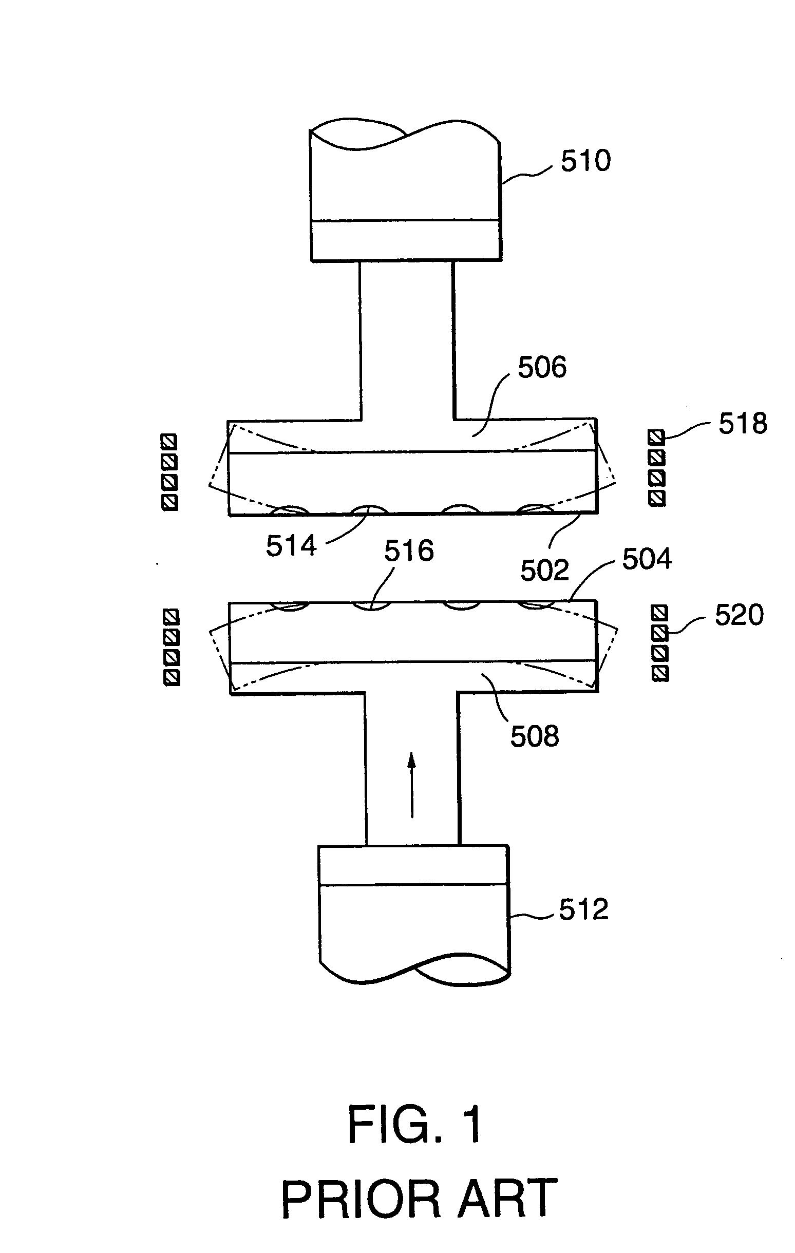
However, such design of the mother mold is disadvantageous in the following respects.
This results in occurrence of tilt in molded products, such as optical lenses, and thickness deviation of the formed products.
Recently, the problem of warp of the mother mold becomes more and more serious.
If press molding is performed in the state where the upper and the lower molds are warped, defective molding may be caused and the upper or the lower mother mold 502 or 504 may be damaged.
If the required product specification is strict, a desired performance may not be achieved.

Method used


Image

  • Press molding apparatus and press molding method
  • Press molding apparatus and press molding method
  • Press molding apparatus and press molding method

Examples


first embodiment

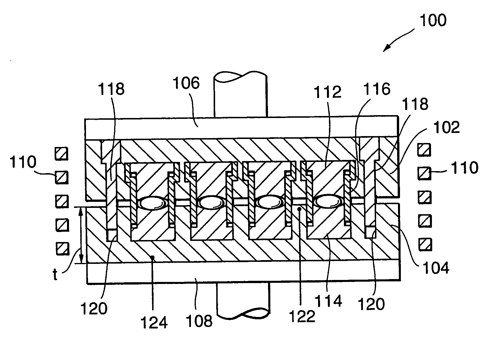
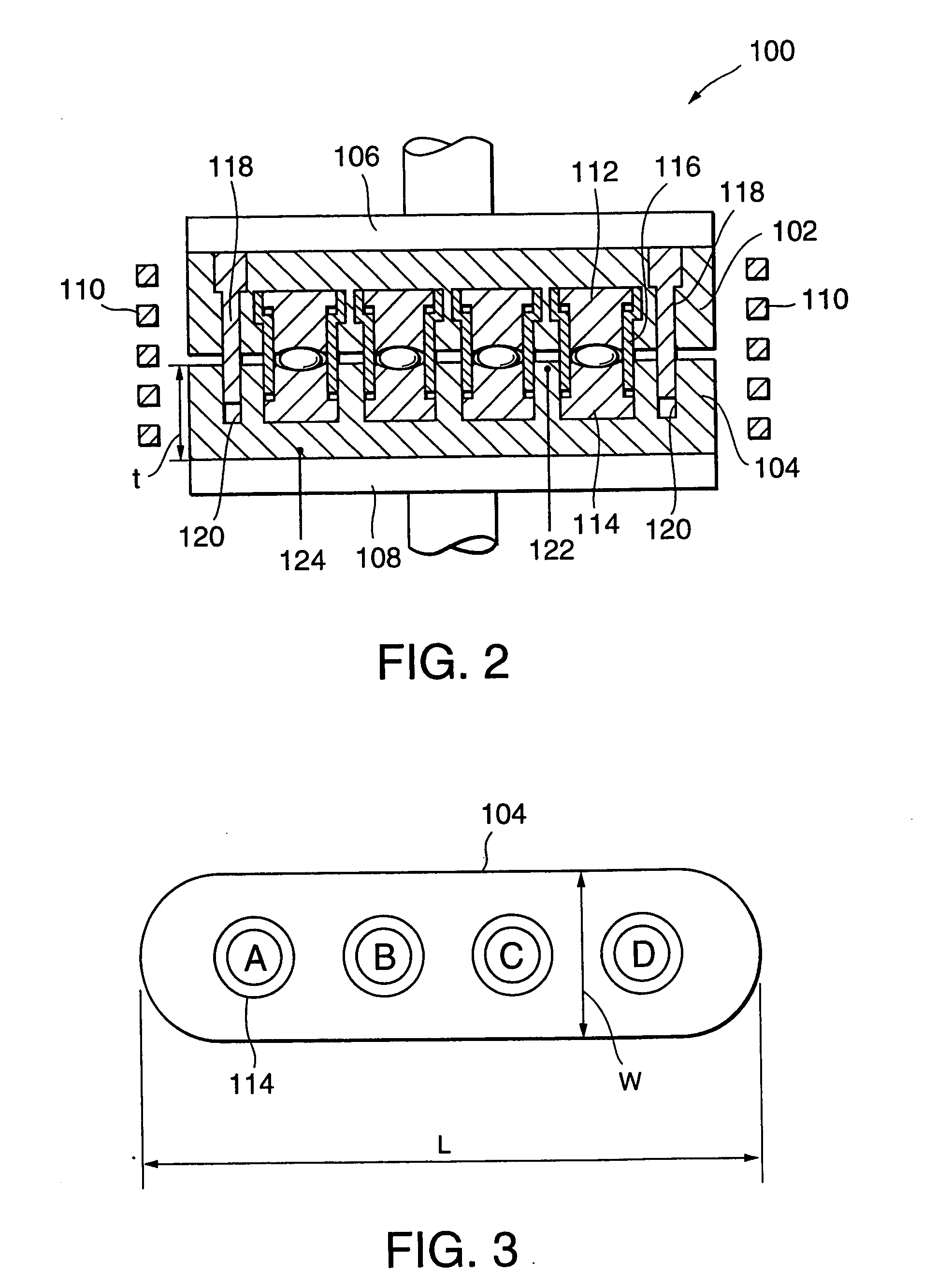
[0045] At first referring to FIG. 2, a press molding apparatus 100 according to this invention will be described. The press molding apparatus 100 is used to produce an optical lens having a predetermined shape by press molding a preform prepared by preliminarily forming a glass material into a flat spherical shape.

[0046] The press molding apparatus 100 comprises an upper mother mold 102 and a lower mother mold 104 arranged at upper and lower positions and faced to each other. Each of the upper and the lower mother molds 102 and 104 is made of a tungsten alloy and has an elongated shape extending in the transversal or horizontal direction in the figure.

[0047] The upper mother mold 102 has four upper mold members 112 arranged in a single line. Similarly, the lower mother mold 104 has four lower mold members 114 arranged in a single line and faced to the upper mold members 112 of the upper mother mold 102, respectively. The upper mold members 112 have lower surfaces as molding surface...

second embodiment

[0056] The above-mentioned modification (FIG. 5) may be applied to the press molding apparatus 300 according to the Furthermore, the mother mold may be made of a material having a relatively small thermal expansion coefficient α. The thickness t of the mother mold may be appropriately controlled. In any event, by satisfying the formula (1), it is possible to stably and uniformly produce optical elements having sufficient accuracy.

third embodiment

[0057] Referring to FIGS. 7 and 8, description will be made of a press molding apparatus according to this invention. For example, the press molding apparatus is used to produce a medium-aperture lens having a diameter of 17 mm by the use of a preform as a material to be press molded. The preform is prepared by preliminarily forming a glass material into a flat spherical shape. As illustrated in FIG. 7, the press molding apparatus comprises a pressing mold set including an upper mold 102 and a lower mold 104. Each of the upper and the lower molds 102 and 104 has an elongated shape extending in the transversal or horizontal direction in the figure and is made of, for example, a tungsten alloy. The upper and the lower molds 102 and 104 are surrounded by induction heating coils 122 and 124, respectively. The induction heating coils 122 and 124 serve to heat the upper and the lower molds 102 and 104 by high-frequency induction heating, respectively.

[0058] The upper mold 102 comprises a ...


PUM

PropertyMeasurementUnit
viscosityaaaaaaaaaa
viscosityaaaaaaaaaa
diameteraaaaaaaaaa

Abstract

A press molding apparatus includes upper and lower mother molds 102 and 104. Each of the mother molds 102 and 104 has four molding surfaces arranged in a single line and satisfies the relationship given by L×α×ΔT / t<0.0008, where L represents the length, t, the thickness, α, the thermal expansion coefficient, and ΔT, the temperature difference between both ends in the thickness direction during induction heating. The press molding apparatus may include a pressing mold set including upper mother molds 102a and 102b attached to a common fixed shaft 118 through upper supporting shafts 110a and 110b and lower mother molds 104a and 104b driven by a common drive shaft 120 through lower supporting shafts 112a and 112b. The upper mother molds 102a and 102b and the lower mother molds 104a and 104b are collectively heated by induction heating coils 122 and 124, respectively.

Description

BACKGROUND OF THE INVENTION [0001] This invention relates to a press molding apparatus and a press molding method for use in precision pressing in which an optical element is obtained by press molding a material, such as a preformed glass material in a heated and softened state and, in particular, to precision pressing in which no polishing is required after molding. [0002] Recently, in a field of production .of an optical element such as an optical lens, it is desired to obtain a high-accuracy lens shape without carrying out surface polishing. To this end, proposal is made of a method comprising the steps of preparing a pre-shaped glass material (preform), heating and softening the preform, and pressing the preform by a high-accuracy pressing surface (Japanese Unexamined Patent Publication JP 2001-10829 A). In particular, use is recently made of a mother mold having an elongated shape with a plurality of molding surfaces arranged in a single line so as to simultaneously press form ...

Claims


Application Information

Patent Timeline
Patent Type & Authority Applications(United States)
IPC IPC(8): B29C33/24B29C43/02B29C43/36B29D11/00C03B11/08C03B11/12
CPCB29C33/08B29C33/24B29C43/021B29C43/36B29D11/00413B29K2709/08C03B2215/80B30B15/34C03B11/08C03B11/125C03B2215/60C03B2215/72B29L2011/0016Y02P40/57
Inventor HIROTA, SHINICHIROFUMIMOTO, TADAYUKITAJIMA, HIDEMI
Owner HOYA CORP
Learn More