Organic electroluminescent apparatus

a technology of electroluminescent apparatus and organic el, which is applied in the direction of electroluminescent light sources, electric discharge lamps, envelopes/vessels, etc., can solve the problems of increasing the power consumption of the display, attenuating the light emitted by the organic el device according to the filter method, and advantageously uncomplicated manufacturing process of display, etc., to achieve high purity, high purity, and high purity

Inactive Publication Date: 2005-10-06
SANYO ELECTRIC CO LTD
View PDF7 Cites 33 Cited by
  • Summary
  • Abstract
  • Description
  • Claims
  • Application Information

AI Technical Summary

Benefits of technology

[0022] The second color temperature region preferably corresponds to the color temperature range from 4500 K to 8500 K. In this way, the fourth filter can convert white light emitted from the organic electroluminescent device into white light with high purity.
[0023] The second color temperature region more preferably corresponds to the color temperature range from 5500 K to 7500 K. In this way, the fourth filter can convert white light emitted from the organic electroluminescent device into white light with higher purity.
[0024] The second color temperature region even more preferably corresponds to the color temperature range from 6000 K to 7000 K. In this way, the fourth filter can convert white light emitted from the organic electroluminescent device into white light with even higher purity.
[0025] The third and fourth filters preferably have a transmittance of at most 30% in a wavelength region of less than 400 nm. In this way, functional degradations of the organic layers caused by ultraviolet radiation can be prevented.
[0026] According to the invention, the use of the first to fourth filters allows white light to be obtained with reduced power consumption.

Problems solved by technology

According to the above described filter method, only an organic EL device for a single color is necessary, and therefore the process of manufacturing the display is advantageously uncomplicated.
However, light emitted from the organic EL device according to the filter method is attenuated as it passes through the three primary color filters.
This increases the power consumption by the display.

Method used


Image

  • Organic electroluminescent apparatus
  • Organic electroluminescent apparatus
  • Organic electroluminescent apparatus

Examples


examples

[0068] In the following example, an organic EL apparatus according to the embodiment was evaluated.

Inventive Example

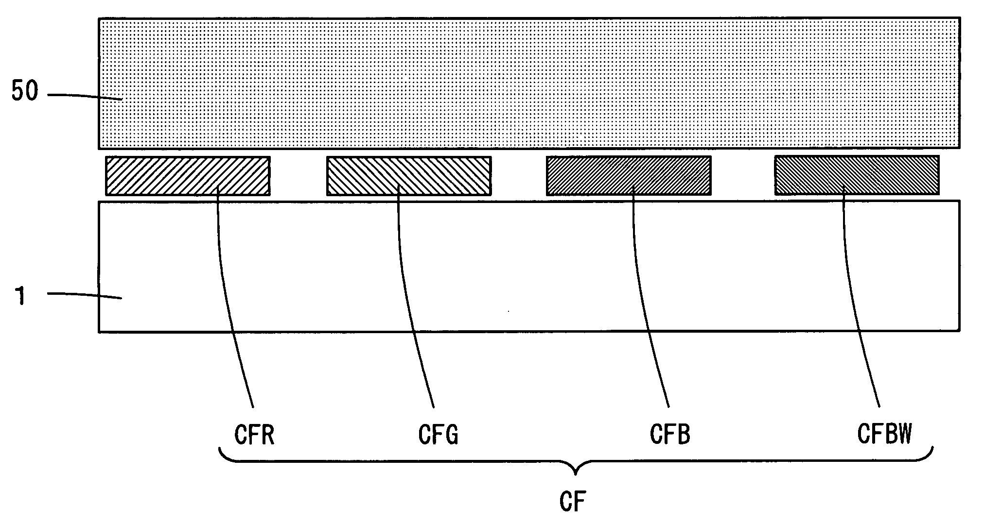
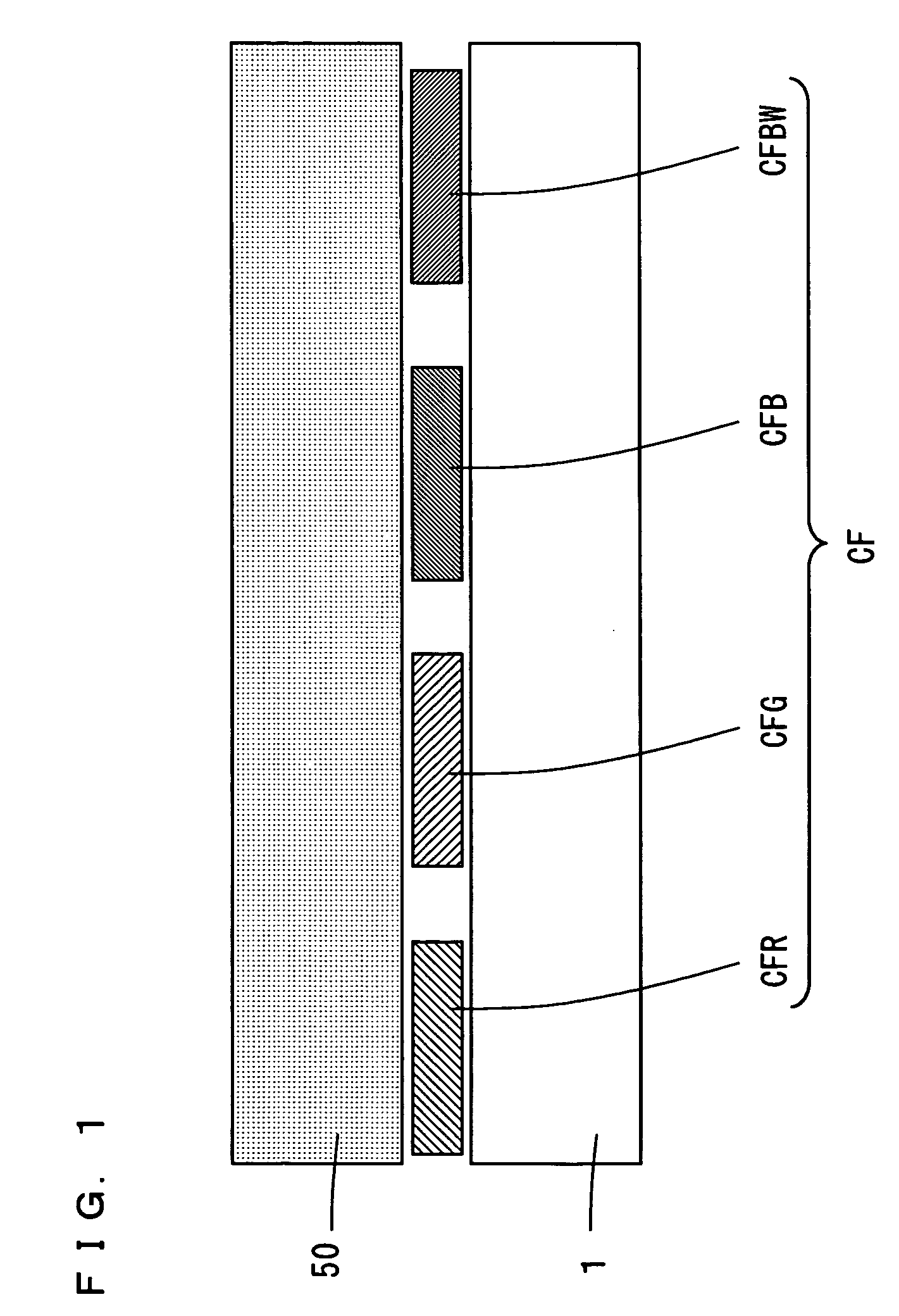
[0069] In this example, a red color filter layer CFR, a green color filter layer CFG, a blue color filter layer CFB, and a blue-green color filter layer CFBW having the following characteristics were used.

[0070] FIGS. 5 to 8 are graphs showing the wavelength-transmittance characteristics for the red color filter layer CFR, the green color filter layer CFG, the blue color filter layer CFB, and the blue-green color filter layer CFBW, respectively. In the graphs in FIGS. 5 to 8, theordinate represents the transmittance and the abscissa represents the wavelength.

[0071] As shown in FIG. 5, the red color filter layer CFR has a transmittance of at least 70% in the wavelength range of 600 nm or more. As shown in FIG. 6, the green color filter layer CFG has a transmittance of at least 70% in the wavelength range from 495 nm to 555 nm.

[0072] As shown in FIG. 7, the blue col...


PUM


Abstract

An organic electroluminescent apparatus essentially includes an organic electroluminescent device, a color filter layer and a substrate. The color filter layer is made of four layers, a red color filter layer, a green color filter layer, a blue color filter layer, and a blue-green color filter layer. The color filter layer is formed between the organic EL device and the substrate. The blue-green color filter layer converts white light emitted from a light emitting layer at a color temperature in the range from 3000 K to 4500 K into white light having high purity at a color temperature of 6500 K.

Description

BACKGROUND OF THE INVENTION [0001] 1. Field of the Invention [0002] The present invention relates to an organic electroluminescent apparatus including a plurality of organic electroluminescent devices. [0003] 2. Description of the Background Art [0004] In recent years, with the advent of advanced information technology, there has been an increasing need for a thin type display capable of full-color display. Displays using an organic electroluminescent device (hereinafter referred to as “organic EL device”) have actively been researched and developed as such a thin type display. The display using an organic EL device is thin and lightweight and has middle to high efficiency and no viewing angle dependency. [0005] In the organic EL device, electrons and holes are injected into a light emitting portion from an electron injection electrode and a hole injection electrode, respectively. These electrons and holes are recombined in the luminescent center, so that organic molecules are excit...

Claims


Application Information

Patent Timeline
Patent Type & Authority Applications(United States)
IPC IPC(8): H01L27/32G02B5/20H01L51/50H05B33/02H05B33/12H05B33/14
CPCH01L27/3213H01L51/5036H01L27/3244H01L27/322H10K59/351H10K59/38H10K59/12H10K50/125
Inventor SAITO, NOBUO
Owner SANYO ELECTRIC CO LTD
Why Eureka
Try Eureka