

Lamp, method of fabricating the same and liquid crystal display apparatus having the same
a technology of liquid crystal display and manufacturing method, which is applied in the manufacture of electric discharge tubes/lamps, discharge tubes luminescnet screens, instruments, etc., can solve the problem of high power consumption of ccfl, and achieve the effect of preventing the reduction of light efficiency and reducing power consumption
- Summary
- Abstract
- Description
- Claims
- Application Information
AI Technical Summary
Benefits of technology
Problems solved by technology
Method used
Image

Examples
first embodiment
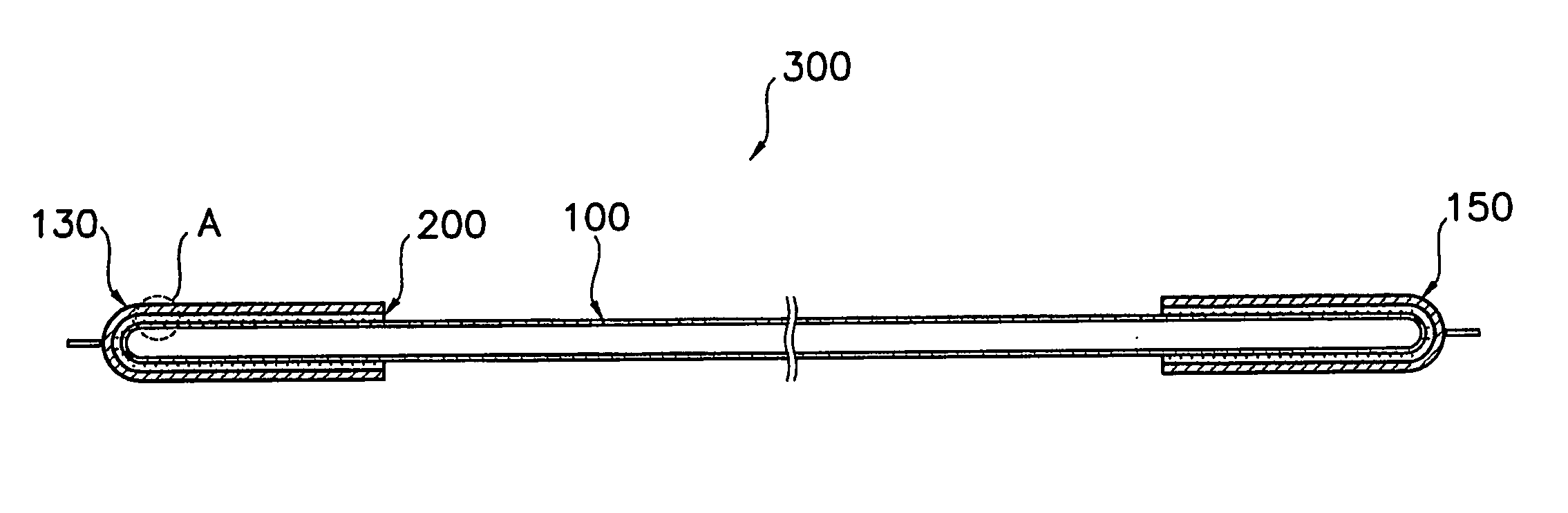
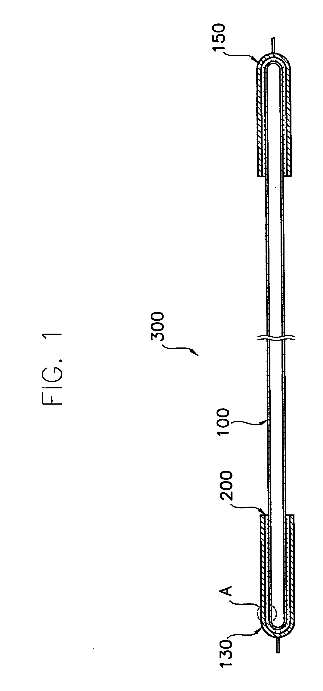
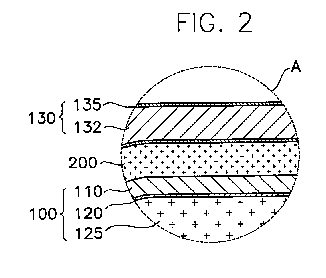
[0033]FIG. 1 is a cross-sectional view showing a lamp according to the present invention. FIG. 2 is a partially enlarged view showing the lamp shown in FIG. 1.
[0034] Referring to FIG. 1, a lamp includes a lamp tube 100 for emitting a light, a first and a second electrodes 130 and 150 for supplying a power voltage to the lamp tube 100, and an adhesive member 200. The adhesive member 200 is disposed between the lamp tube 100 and the first electrode 130, and between the lamp tube 100 and the second electrode 150. At least one of the first and the second electrodes 130 and 150 is disposed on an outer surface of the lamp tube 100. The adhesive member 200 includes a silver component.
[0035] Referring to FIG. 2, the lamp tube 100 includes a tube body 110, a fluorescent material layer 120 and a discharge gas 125. The tube body 110 having a predetermined dielectric constant is made of a glass and provides a discharge space. The fluorescent material layer 120 having a predetermined thickness ...
second embodiment
[0039] In FIG. 3, a first electrode according to the present invention is indicated by a reference numeral “136”.
[0040] Referring to FIG. 3, the first electrode 136 has a pipe shape that covers the outer surface of the tube body 110, and is separated from the outer surface of the tube body 110 in a predetermined distance. The first electrode 136 has a first end portion 136a and a second end portion 136b opposite to the first end portion 136a. The first and second end portions 136a and 136b are opened to engage with the tube body 110 of the lamp tube 100. The adhesive member 200 having the silver component is interposed between the outer surface of the tube body 110 and the first electrode 136.
[0041] The adhesive member 200 includes a silver grain, a resin having an adhesive strength for maintaining a shape of the silver grain and a volatility solvent for hardening the resin. The adhesive member 200 further includes an antioxidant for preventing the silver grain from being oxidized....
fifth embodiment
[0049] However, at the present invention in FIG. 8, voids can be formed between the lamp tube 100 and the first electrode 137 in comparison with the embodiments in FIGS. 3, 4 and 5. When voids is formed between the lamp tube 100 and the first electrode 137, the area acting as a electrode decreases and the power consumption increases.
[0050] This is because the volatile solvent volatilized from the adhesive member 200 cannot be exhausted rapidly from the space between the first electrode 137 and the lamp tube 100 toward an exterior of the first electrode 139.
[0051] The first electrode 137 of the embodiment in FIG. 8 has an electrode area larger than that of the first electrode 136 of the embodiment in FIG. 5. However, voids can be formed in the embodiment of FIG. 8 more easily than in the embodiment of FIG. 5. The first electrode 136 of the embodiment in FIG. 5 has an electrode area smaller than that of the first electrode 137 of the embodiment in FIG. 8. However, it is more difficul...
PUM
| Property | Measurement | Unit |
|---|---|---|
| temperature | aaaaa | aaaaa |
| temperature | aaaaa | aaaaa |
| power voltage | aaaaa | aaaaa |
Abstract
Description
Claims
Application Information