Organic electroluminescent display

a technology of electroluminescent display and electroluminescent screen, which is applied in the direction of discharge tube luminescnet screen, discharge tube/lamp details, electric discharge lamps, etc., can solve the problems of complex fabrication process, and achieve good color balance and high color purities

Active Publication Date: 2005-10-06
SANYO ELECTRIC CO LTD
View PDF3 Cites 41 Cited by
  • Summary
  • Abstract
  • Description
  • Claims
  • Application Information

AI Technical Summary

Benefits of technology

[0011] An object of the present invention is to provide an organic electroluminescent display which can offer emissions of red, green, and blue lights with high color purities that maintain a good color balance.
[0014] It is preferred that a ratio of an intensity value of the light emitted from the light emitting layer at a wavelength of 575 nm to an intensity value of the light emitted from the light emitting layer at a wavelength of 475 nm is not less than 0.4 and not more than 4.0. This results in emissions of red, green, and blue lights with higher color purities that maintain a good color balance.
[0015] It is preferred that a ratio of a luminance value of the light passed through the third color filter to a luminance value of the light passed through the first color filter is not less than 0.37 and not more than 2.73. This results in emissions of red, green, and blue lights with even higher color purities that maintain a good color balance.
[0016] It is preferred that a ratio of a luminous efficiency of the light passed through the third color filter to a luminous efficiency of the light passed through the first color filter is not less than 0.37 and not more than 2.73. This results in emissions of red, green, and blue lights with still higher color purities that maintain a good color balance.
[0017] The light emitting layer may include a first light emitting layer that emits light with a peak intensity in a wavelength range of not less than 550 nm and not more than 640 nm and a second light emitting layer that emits light with a peak intensity in a wavelength range of not less than 460 nm and not more than 510 nm. In this manner, light having peak intensities in the wavelength range of not less than 460 nm and not more than 510 nm and wavelength range of not less than 550 nm and not more than 640 nm, respectively, can be efficiently obtained.
[0018] The organic electroluminescent display according to the present invention can offer emissions of red, green, and blue lights with high color purities that maintain a good color balance.

Problems solved by technology

This makes the fabrication processes complicated.

Method used


Image

  • Organic electroluminescent display
  • Organic electroluminescent display
  • Organic electroluminescent display

Examples


##ventive example 1

Inventive Example 1

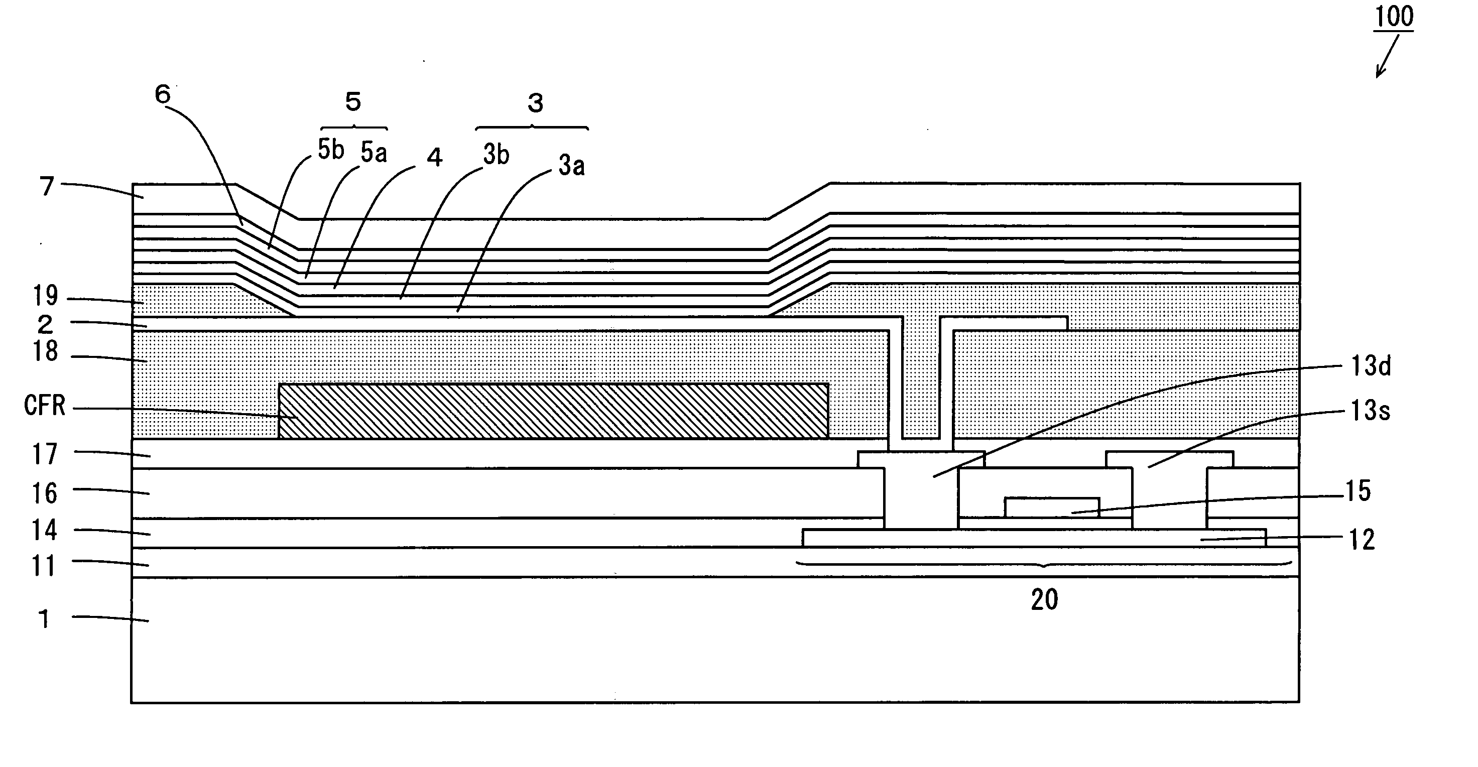
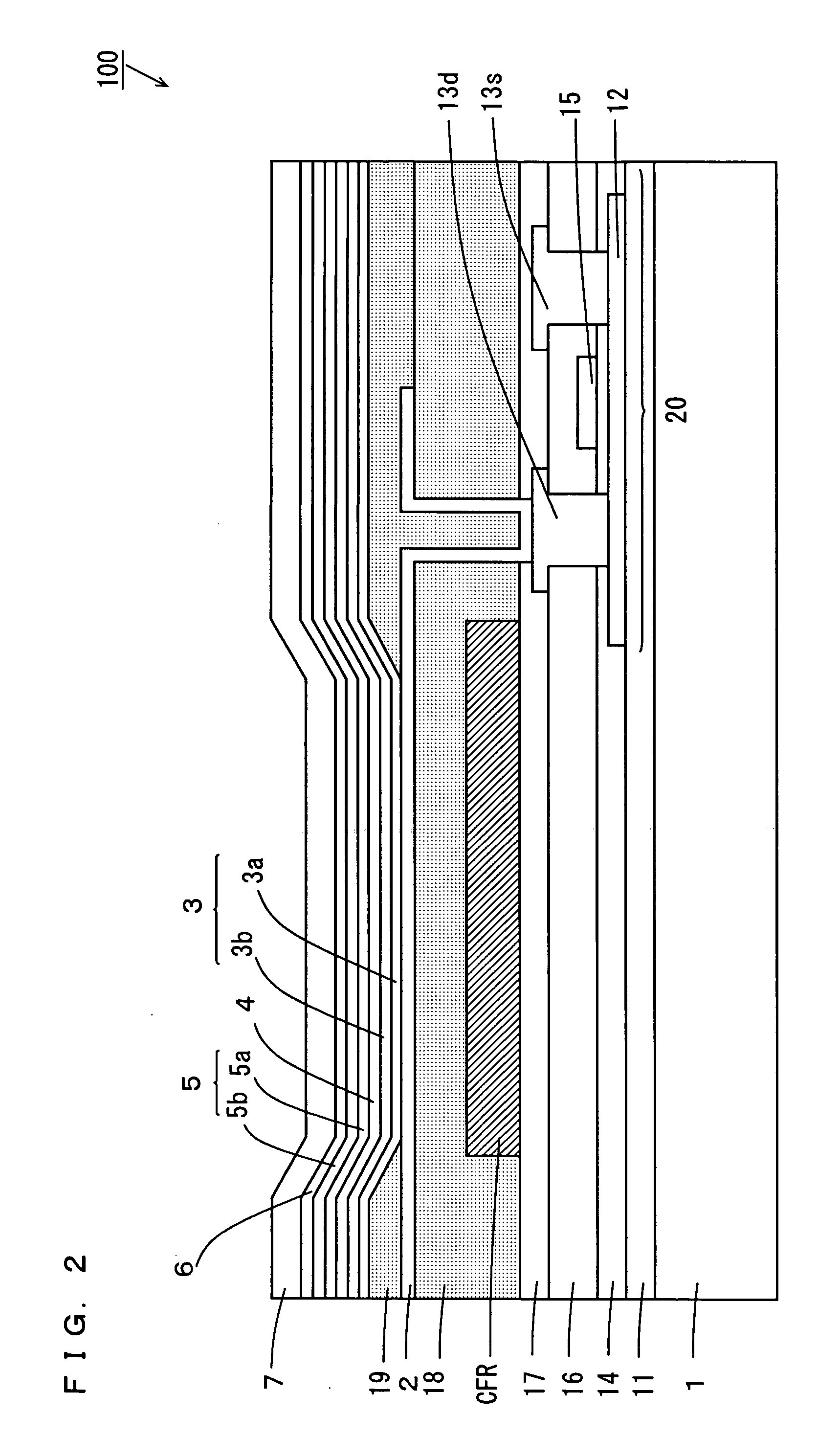
[0066] The organic EL display of the inventive example 1 is similar in structure to the organic EL display 100 of the embodiment.

[0067]FIG. 3 is an explanatory diagram that shows the emission spectrum of the light emitting layer 5 in the organic EL display 100.

[0068] The light emitting layer 5 produces light having peak intensities in a wavelength range of not less than 460 nm and not more than 510 nm and a wavelength range of not less than 550 nm and not more than 640 nm, respectively, as shown in FIG. 3.

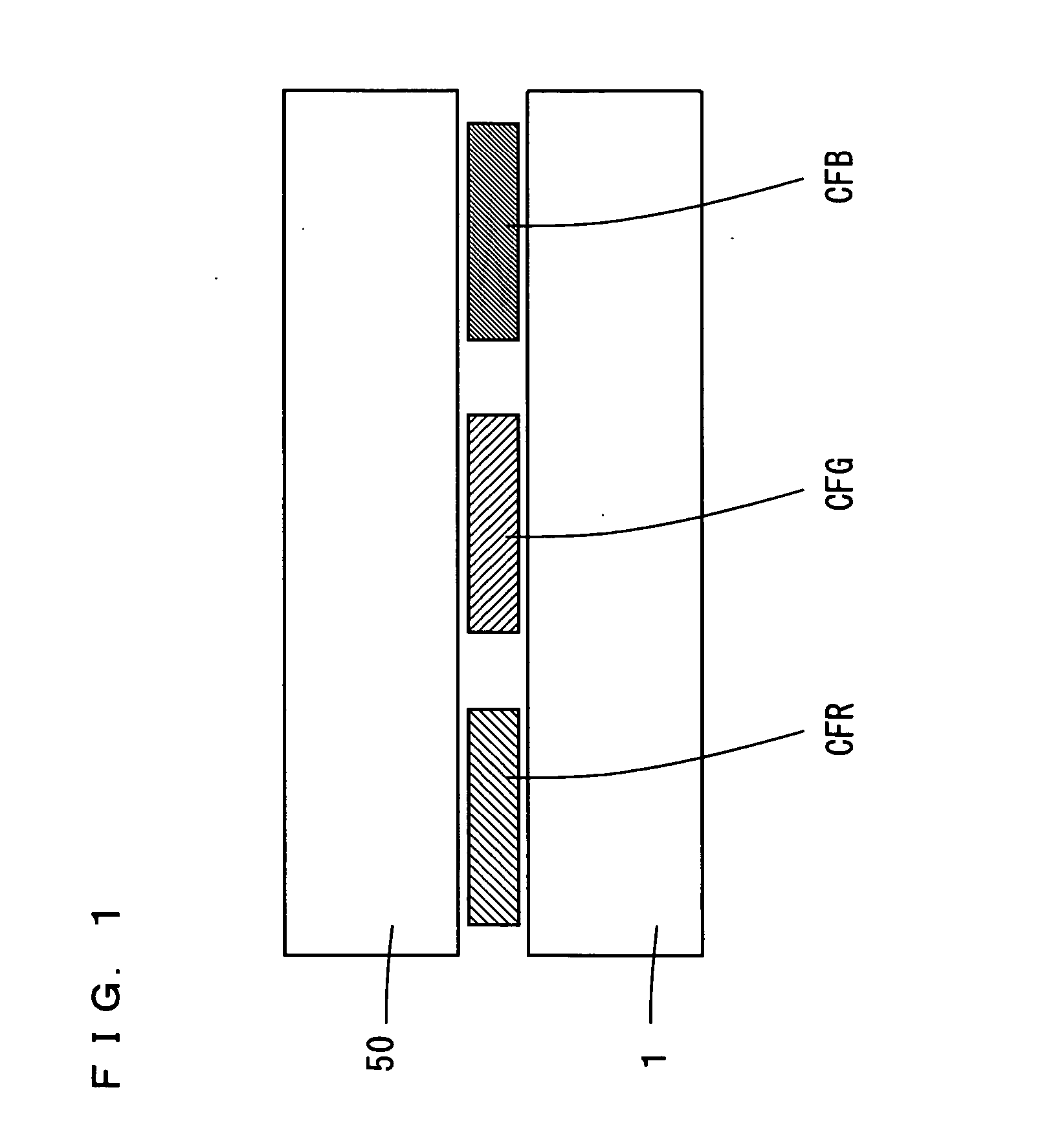
[0069]FIG. 4 is an explanatory diagram that shows the transmittances of the red color filter layer CFR, green color filter layer CFG, and blue color filter layer CFB in the organic EL display 100.

[0070] The red color filter layer CFR has a transmittance of 50% or more in a wavelength range of not less than 580 nm and not more than 660 nm and a transmittance of 10% or less in a wavelength range of not less than 400 nm and not more than 550 nm. The green color ...

##ventive example 2

Inventive Example 2

[0084] The differences between the organic EL display of the inventive example 2 and the organic EL display 100 used in the inventive example 1 will be described referring to the drawings below.

[0085]FIG. 6 is an explanatory diagram that shows the intensities of the emission spectrum of the light emitting layer 5 in the organic EL display of this inventive example.

[0086] The light emitting layer 5 produced light having peak intensities in a wavelength range of not less than 460 nm and not more than 510 nm and in a wavelength range of not less than 550 nm and not more than 640 nm, respectively. The luminous efficiency of the light was 13.4 cd / A.

[0087] The ratio of an intensity value of the light emitted from the light emitting layer 5 at a wavelength of 575 nm to an intensity value of the light emitted at a wavelength of 475 nm (which will hereinafter be referred to as an intensity ratio) was 1.47.

[0088] The luminous efficiencies of the lights passed through th...

##ventive example 3

Inventive Example 3

[0094] The differences between the organic EL display of the inventive example 3 and the organic EL display used in the inventive example 2 will be described referring to the drawings below.

[0095]FIG. 8 is an explanatory diagram that shows the intensities of the emission spectrum of the light emitting layer 5 in the organic EL display of this inventive example.

[0096] As shown in FIG. 8, the light emitting layer produced light having peak intensities in a wavelength range of not less than 460 nm and not more than 510 nm and in a wavelength range of not less than 550 nm and not more than 640 nm, respectively. The luminous efficiency of the light was 12.1 cd / A. The intensity ratio was 1.00.

[0097] The luminous efficiencies of the lights passed through the red color filter layer CFR, green color filter layer CFG, and blue color filter layer CFB, respectively, were measured with a luminance meter. The luminous efficiency of the light passed through the red color filt...


PUM


Abstract

A light emitting layer produces light having peak intensities in a wavelength range of not less than 460 nm and not more than 510 nm and a wavelength range of not less than 550 nm and not more than 640 nm, respectively. Each of a red color filter layer, green color filter layer, and blue color filter layer has a transmittance of 50% or more in a prescribed wavelength range and a transmittance of 10% or less in a prescribed wavelength range. The ratio of an intensity value of the light emitted from the light emitting layer at a wavelength of 575 nm to an intensity value of the light emitted at a wavelength of 475 nm is not less than 0.4 and not more than 4.0.

Description

BACKGROUND OF THE INVENTION [0001] 1. Field of the Invention [0002] The present invention relates to an organic electroluminescent display using a plurality of organic electroluminescent devices. [0003] 2. Description of the Background Art [0004] With the recent diversification of information equipment, there is a growing need for flat panel displays that require lower power consumption than commonly used CRTs (cathode ray tubes). As one of the flat panel displays, organic electroluminescent devices (hereinafter abbreviated to organic EL devices) with such features as high efficiency, thinness, lightweight, and low viewing angle dependency, have attracted attention. Displays using such organic EL devices are actively being developed. [0005] An organic EL device is a self-emitting type of device. In the organic EL device, an electron injection electrode and a hole injection electrode inject electrons and holes, respectively, to a luminescent portion, where the injected electrons and ...

Claims


Application Information

Patent Timeline
Patent Type & Authority Applications(United States)
IPC IPC(8): H01L27/32G02B5/20H01L51/50H05B33/00H05B33/12H05B33/14
CPCH01L27/3244H01L27/322H10K59/38H10K59/12
Inventor HAMADA, YUJI
Owner SANYO ELECTRIC CO LTD
Why Eureka
Try Eureka