
System and method for monitoring of insulation condition

a technology of insulation condition and monitoring system, which is applied in the direction of emergency protective arrangements for limiting excess voltage/current, testing circuits, instruments, etc., can solve the problems of winding insulation, electrical equipment damage, and insulation system breakdown, etc., to achieve the effect of preventing damage and deterioration

Inactive Publication Date: 2005-10-06
GENERAL ELECTRIC CO
View PDF12 Cites 43 Cited by
  • Summary
  • Abstract
  • Description
  • Claims
  • Application Information

AI Technical Summary

Problems solved by technology

Insulating systems may break down for many reasons, jeopardizing the continued operation of electrical equipment.
The winding insulation, for example, for electric machines is subject to damage and deterioration caused by thermal, electrical, mechanical, chemical and environmental stresses.
Typical insulation failure occurs in the slot section between turns or between the coil and ground, and at end windings between coils of adjacent phases.
Winding insulation degradation can result in acceleration of machine failure, which decreases the service life of the machine and results in increased costs due to repair or replacement cost and loss of revenue due to machine outage.
However, these conventional off-line techniques can be intrusive and costly since it is required that the electrical machine be shut down and taken out of service to perform the required diagnostic test and / or measurement.
The regular machine maintenance is typically performed once every 3-6 years; therefore, the off-line stator insulation condition cannot be evaluated frequently enough to guarantee reliable operation of the machine until the next outage.
One major drawback of these methods is that the monitoring system detects severe fault conditions only after the fault has occurred, making proactive maintenance and servicing difficult.
The on-line partial discharge detects early symptoms of insulation degradation; however, it requires expensive specialized equipment and accurate interpretation of the measurements relies on the skill of an operator.

Method used


Image

  • System and method for monitoring of insulation condition
  • System and method for monitoring of insulation condition
  • System and method for monitoring of insulation condition

Examples


Embodiment Construction

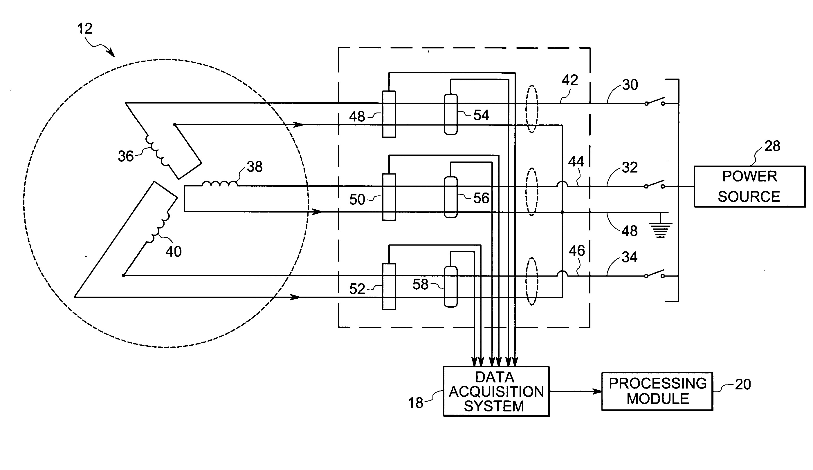
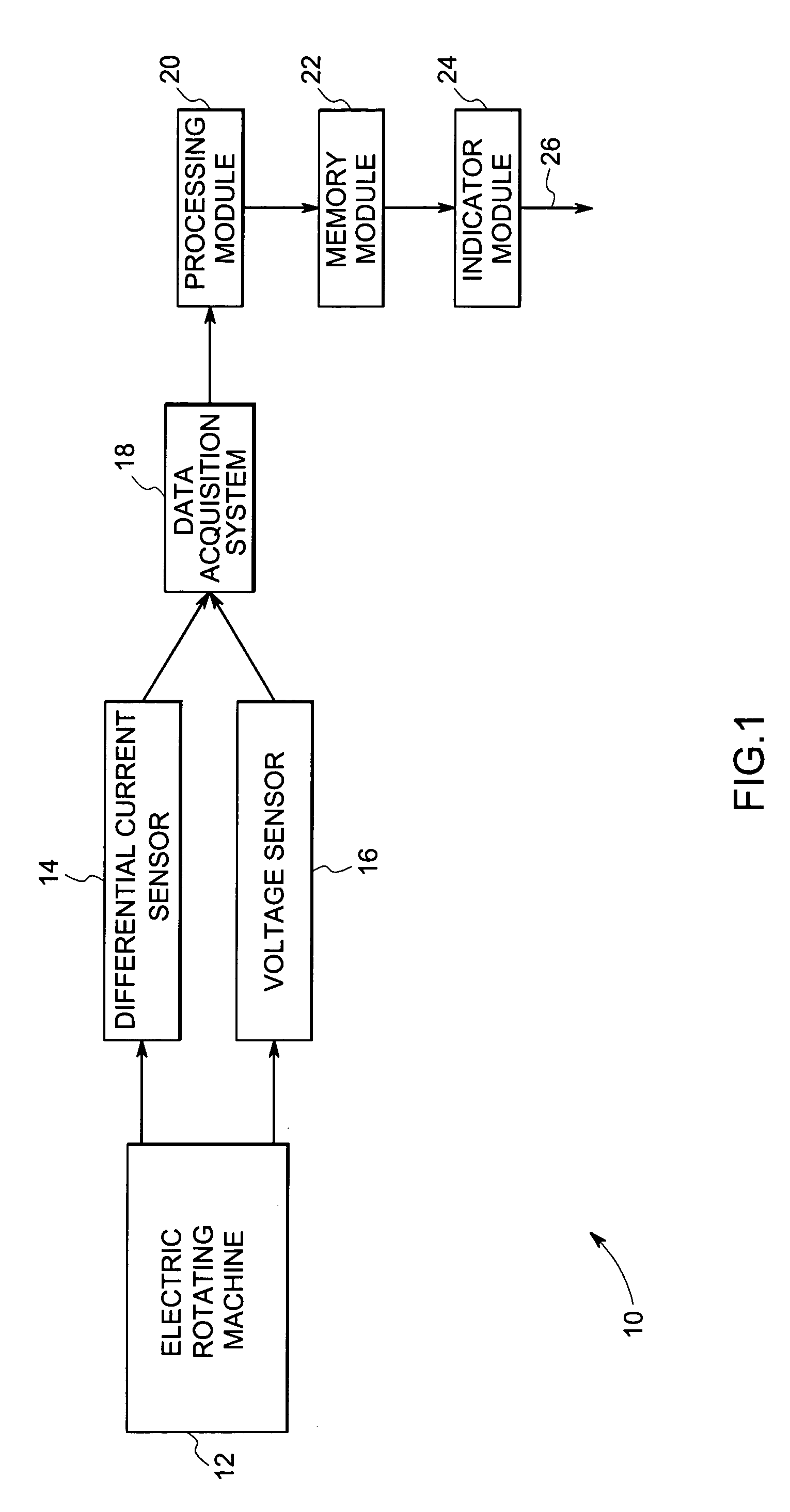
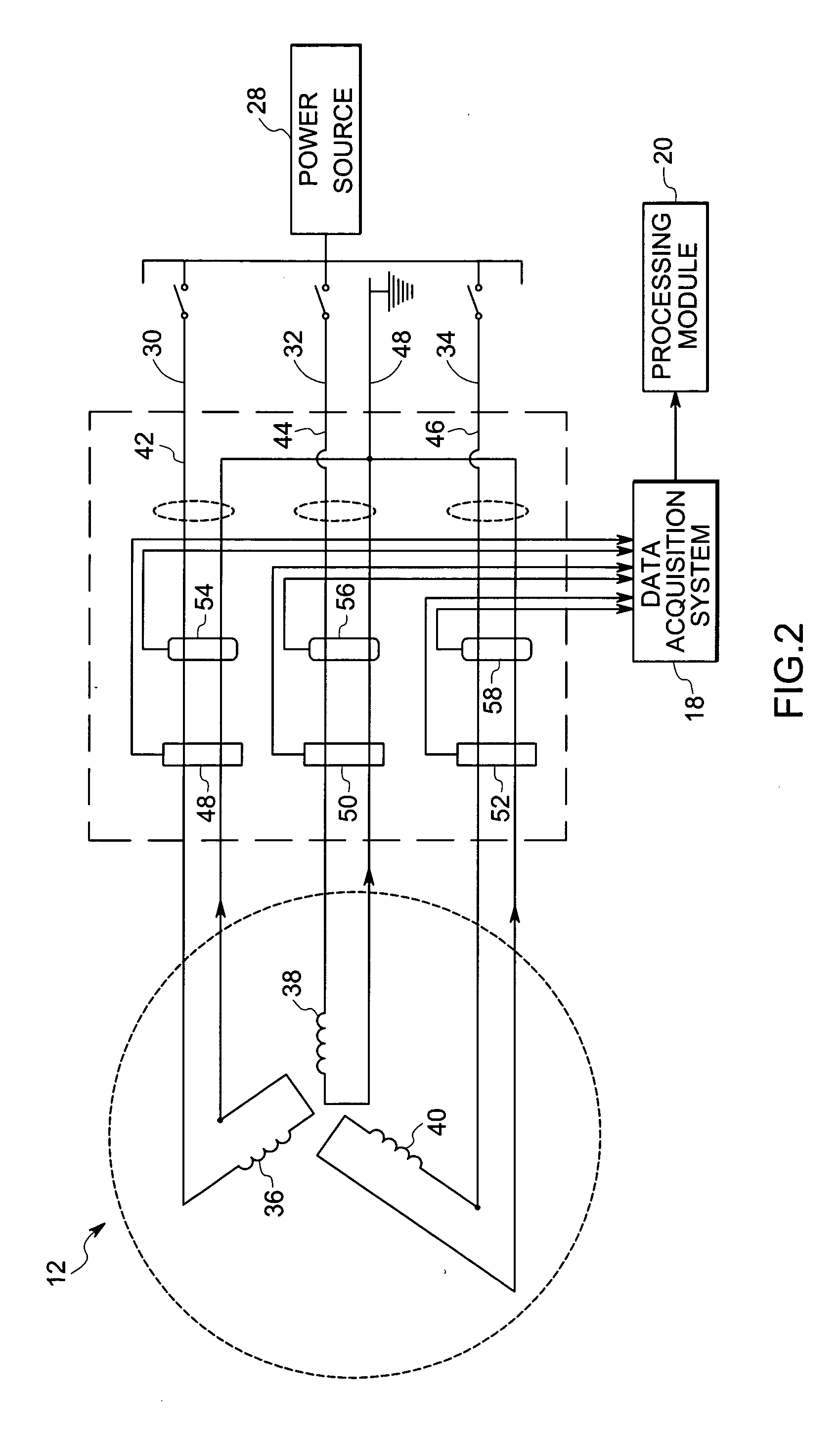
[0015] Referring now to FIG. 1, an online insulation condition monitoring system 10 is illustrated for a rotating electric machine 12, which is typically a motor or a generator. The system 10 comprises a differential current sensor 14 and a voltage sensor 16 coupled to the machine 12, for measuring values for the instantaneous differential current and the instantaneous phase voltage respectively. A data acquisition system 18 enables measurement of signals from the output of the differential current sensor 14 and the voltage sensor 16. The signals are digitized at a sampling frequency sufficient for obtaining the phasor quantities.

[0016] The signals from the sensors 14 and 16, measured by the data acquisition systeml8, are applied to a processing module 20. Module 20 will typically include hardware circuitry and software for performing computations indicative of insulation condition as described below. Module 20 may thus include a range of circuitry types, such as, a microprocessor ...


PUM


Abstract

An online insulation condition monitoring system for a rotating electric machine, includes a differential current sensor and a voltage sensor coupled to the machine, for measuring values for the instantaneous differential current and the instantaneous phase voltage respectively. A processing module is configured for converting the values for the instantaneous differential current and the instantaneous phase voltage to respective values for phasor current and phasor voltage. The processing module further calculates an angular relationship between phasor current and phasor voltage and generates an output based on the calculated angular relationship, as an indication of insulation condition.

Description

BACKGROUND [0001] The present invention relates to insulation condition monitoring, and more specifically to a technique for monitoring of the state of insulation, such as for stator winding insulation condition monitoring. [0002] Many different types of electrical machines employ windings and other conductors that are insulated by various insulation systems. For example, motors and generators commonly include wound rotors and stators, or may include preformed windings or coils. The conductors typically serve either simply to conduct electrical current, or to produce magnetic fields by virtue of the flow of such current. Insulation systems separate conductors and windings from one another, and from adjacent components in the assembled system. Such insulation systems may include various varnish systems, tapes, coatings, sleeves, and so forth, or combinations of these. The integrity of the insulation systems is important to the reliability and life expectancy of the electrical equipme...

Claims


Application Information

Patent Timeline
IPC IPC(8): G01R31/06G01R31/14G01R31/34H01H31/12H02H3/00H02H9/08
CPCG01R31/346G01R31/343
Inventor YOUNSI, ABDELKRIM KARIMKLIMAN, GERALD BURTKLIMAN, EDITH M.SHAH, MANOJ RAMPRASADLEE, SANG BINHOUSE, MICHAEL BRYNNLUSTED, RODERICK MARK
Owner GENERAL ELECTRIC CO
Learn More