Exposure device and exposure method

a technology of exposure device and exposure method, which is applied in the direction of instruments, printing, and processing output data, etc., can solve problems such as image quality declin

Inactive Publication Date: 2005-10-06
NK WORKS CO LTD
View PDF2 Cites 6 Cited by
  • Summary
  • Abstract
  • Description
  • Claims
  • Application Information

AI Technical Summary

Benefits of technology

[0009] It is an object of the present invention to provide an exposure device and an exposure method in which the difference in density between two exposure regions corresponding to two neighboring pixels contained in image data can be reduced.
[0012] With such a structure, the region between the centers of the two exposure regions corresponding to the two neighboring pixels contained in image data is exposed according to the pixel level between the pixel levels of the two neighboring pixels. This reduces the difference in density between the two exposure regions corresponding to the two neighboring pixels on the photosensitive medium. Accordingly, the quality of an image exposed on a photosensitive medium can be improved as compared with that when the region between the centers of the two exposure regions corresponding to the two neighboring pixels contained in image data is exposed according to the pixel level (including the pixel levels of the two neighboring pixels) that is not between the pixel levels of the two neighboring pixels and that when the region between the centers of the two exposure regions is not exposed under the control of the second control means.
[0020] With such a structure, also for the sub scanning direction which is irradiated with the light intermittently (discontinuously) from the light source, the fluctuation in light amount in the regions among multiple pixels is relatively gentle. Accordingly, the difference in density between the two exposure regions corresponding to the two pixels neighboring in the main scanning direction on the photosensitive medium and the difference in density between the two exposure regions corresponding to the two pixels neighboring in the sub scanning direction can be brought close to each other. Consequently, the quality of the image formed on the photosensitive medium can be improved.
[0022] With such a structure, the difference in density between the two exposure regions corresponding to the two neighboring pixels on the photosensitive medium can be reduced effectively. Consequently, the quality of the image formed on the photosensitive medium can be further improved.
[0024] With such a structure, the difference in density between the two exposure regions corresponding to the two neighboring pixels on the photosensitive medium can be reduced more effectively. Consequently, the quality of the image formed on the photosensitive medium can be further improved.

Problems solved by technology

Accordingly, when the case in which an image is viewed along the main scanning direction and the case in which the image is viewed along the sub scanning direction are compared, an image whose edge (the difference in density among dots) is enhanced in the sub scanning direction is produced, posing the problem of decreasing image quality.

Method used


Image

  • Exposure device and exposure method
  • Exposure device and exposure method
  • Exposure device and exposure method

Examples


Embodiment Construction

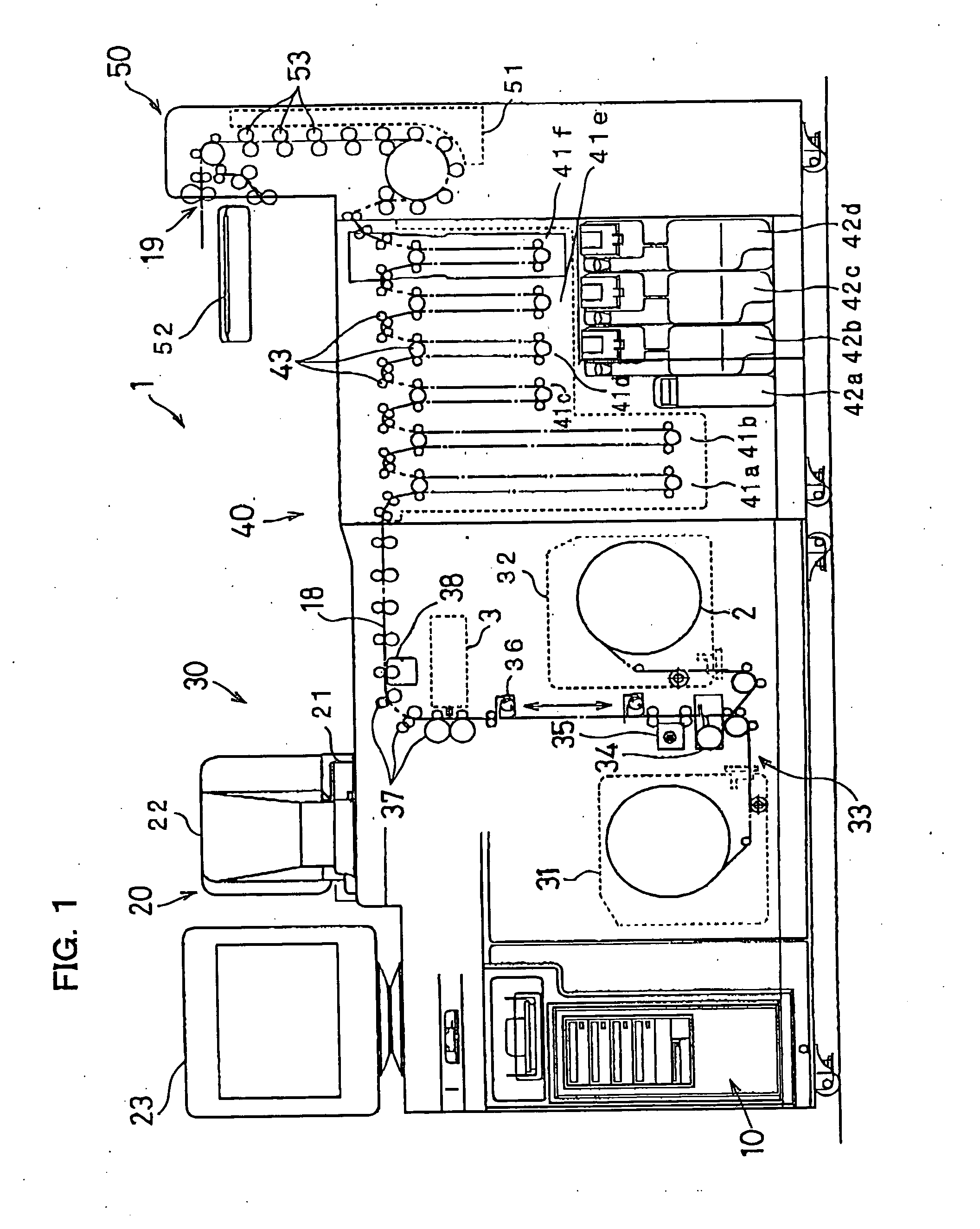
[0033] A preferred embodiment of the present invention will be described herein below with reference to the drawings. FIG. 1 is a schematic diagram of a photographic processor including an exposure device according to an embodiment of the invention.

[0034] A photographic processor 1 shown in FIG. 1 adopts a digital-scan exposure system with a laser beam, which includes a scanner 20, a printer 30, a processor 40, and a finishing section 50. The photographic processor 1 also includes paper magazines 31 and 32. A photographic paper 2 which is a long photosensitive medium accommodated in the paper magazines 31 and 32 is transferred to a cutter 34 (described later) along a path 18 indicated by alternating long and short dashed lines in FIG. 1. The photographic paper 2 which is cut along the width into a specified length with the cutter 34 is transferred along the path 18 from the printer 30 through the processor 40 to the finishing section 50.

[0035] The scanner 20 performs various proce...


PUM


Abstract

In an exposure device according to the present invention, a plurality of exposure bands each containing multiple dots is formed on photographic paper by repeating main scanning in a main scanning direction based on image data that contains multiple pixels and the transfer of the photographic paper in a sub scanning direction. Of the multiple dots contained in each of two continuous exposure bands, the mean value of the pixel levels of two pixels corresponding to two dots with the same positional relationship for the main scanning direction is calculated to derive interpolation data. Thus, the region between the two dots neighboring in the sub scanning direction on the photographic paper is exposed on the basis of the interpolation data.

Description

BACKGROUND OF THE INVENTION [0001] 1. Field of the Invention [0002] The present invention relates to an exposure device and an exposure method for exposing a photosensitive medium to light on the basis of image data including multiple pixels. [0003] 2. Description of Related Art [0004] Photographic processors that adopt what is called a digital exposure system have been recently used extensively. Such a digital exposure system is capable of forming an image by exposing photographic paper to light modulated on the basis of digital image data. The adoption of the digital exposure system allows highly flexible image processing such as color correction, density correction, and sharpening processing and also rapid additional printing, thus providing high-quality printing with high color- and density-reproducibility and high resolution. [0005] An example of the foregoing digital-exposure photographic processors is one that adopts a scanning exposure system in which a laser beam is used fo...

Claims


Application Information

Patent Timeline
Patent Type & Authority Applications(United States)
IPC IPC(8): B41J2/44G02B26/10G02B26/12G06K15/02
CPCG06K2215/0071G06K15/02
Inventor EHARA, TAKUJINAKAHARA, FUMIHIRO
Owner NK WORKS CO LTD
Why Eureka
Try Eureka