Fabrication method for an in-stack stabilized synthetic stitched CPP GMR head

Inactive Publication Date: 2005-10-06
HEADWAY TECH INC
View PDF8 Cites 18 Cited by
  • Summary
  • Abstract
  • Description
  • Claims
  • Application Information

AI Technical Summary

Benefits of technology

[0015] The first object of this invention is to provide an in-stack biased CPP synthetic spin-valve sensor in which the biasing exchange field is suffi

Problems solved by technology

One of the problems associated with the design of a good spin valve sensor is the stabilization of its magnetically free layer.
This domain structure is not fixed in time, however, but moves randomly as a result of thermal agitation and/or external fields, leading to a form of noise in the sensor signal called Barkhausen noise.
It must be pointed out, however, that as the width of the sensor (its “trackwidth”) becomes narrower, the longitudinal biasing effect of the laterally positioned magnets can actually impede the free movement of the free layer magnetic moment as it responds to external magnetic fields.
In the CPP configuration, however, placing conducting permanent

Method used


Image

  • Fabrication method for an in-stack stabilized synthetic stitched CPP GMR head
  • Fabrication method for an in-stack stabilized synthetic stitched CPP GMR head
  • Fabrication method for an in-stack stabilized synthetic stitched CPP GMR head

Examples


Example

[0031] The present invention provides a CPP synthetic spin-valve sensor having a stitched configuration, a pillar portion on which is formed a portion of larger cross-sectional area. The longitudinal bias layer within this sensor is formed in two portions: one portion being within the pillar, proximate to the free layer but separated from it by a decoupling layer to prevent exchange coupling between the biasing layer and the free layer, the other portion being a tri-layer entirely within the stitched portion of the sensor, which tri-layer acts as a synthetic pinning structure.

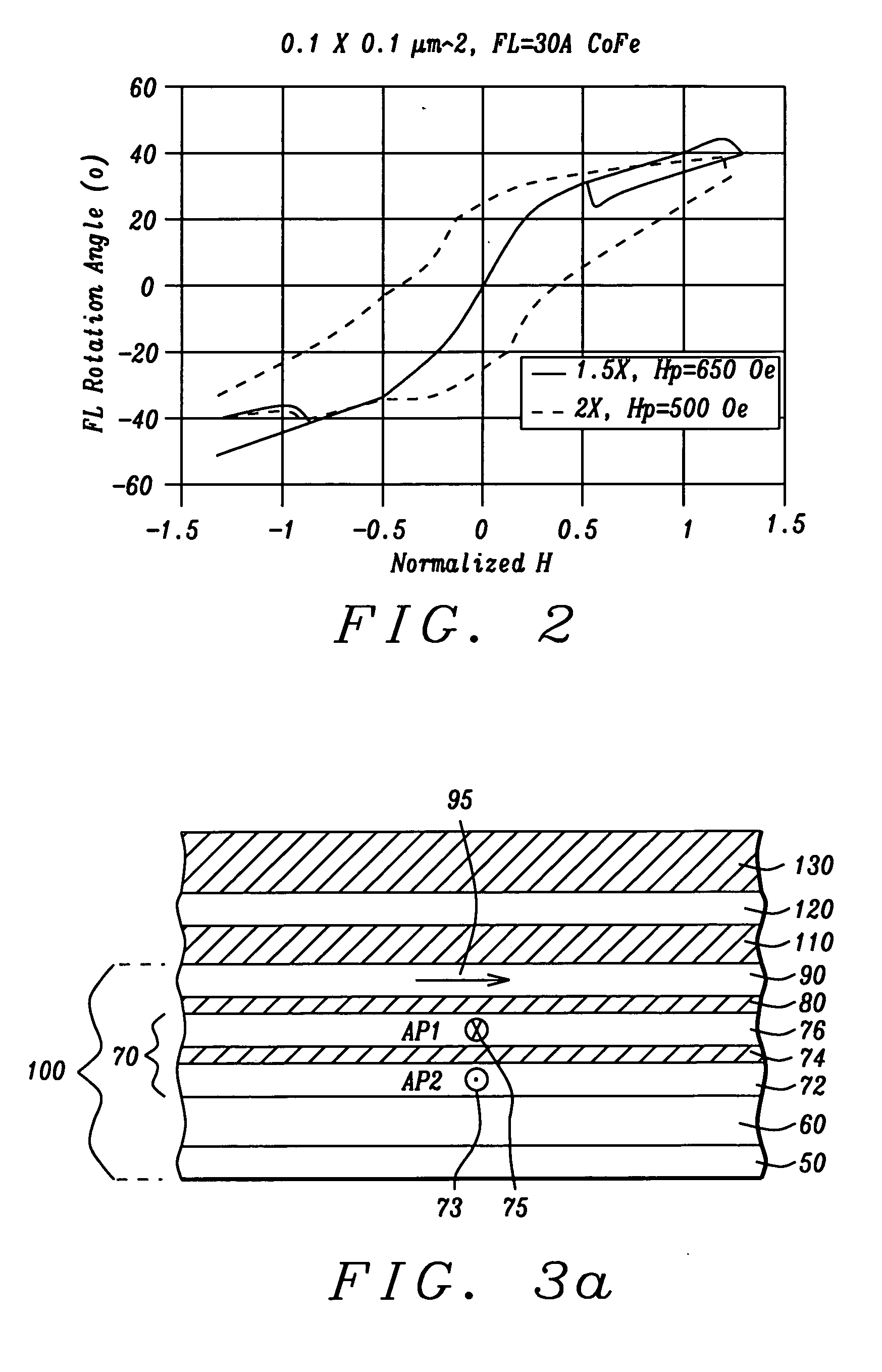
[0032] Referring now to FIG. 3a, there is shown an ABS cross-sectional view of the configuration of layers (the stack) that will become the pillar portion of the sensor. This portion comprises the CPP synthetic spin-valve portion (SySV) (100), on which is formed the decoupling layer (110), the LBL layer (120) and a first capping layer (130). The decoupling layer is a trilayer of Cu / Ta / Cu, wherein both Cu layer...


PUM

PropertyMeasurementUnit
Temperatureaaaaaaaaaa
Timeaaaaaaaaaa

Abstract

A method for fabricating a stitched CPP synthetic spin-valve sensor with in-stack stabilization of its free layer. The method can also be applied to the formation of a stitched tunneling magnetoresistive sensor. The free layer is strongly stabilized by magnetostatic coupling through the use of a longitudinal biasing formation that includes a ferromagnetic layer, denoted LBL, within the pillar portion of the sensor and a synthetic exchange coupled tri-layer within the stitched portion of the sensor. The tri-layer consists of two ferromagnetic layers, FM1 and FM2 separated by a coupling layer and magnetized longitudinally in antiparallel directions. A criterion for the magnetic thicknesses of the layers: [t(LBL)+t(FM1)]/t(FM2)=70/90 angstroms of CoFe insures a strong exchange coupling. The magnetization of the tri-layer is done in a low field anneal that does not disturb the previous magnetization of the ferromagnetic free layer.

Description

BACKGROUND OF THE INVENTION [0001] 1. Field of the Invention [0002] This invention relates generally to the fabrication of a giant magnetoresistive (GMR) magnetic field sensor in the current-perpendicular-to-plane (CPP) configuration, more specifically to the stabilization of the magnetization of the free layer of such a sensor. [0003] 2. Description of the Related Art [0004] The synthetic (Sy) spin-valve (SV) giant magnetoresistive (GMR) sensor is a multi-layered configuration of magnetic and non-magnetic layers which includes a magnetically free layer, whose magnetic moment is free to respond to outside magnetic stimuli, separated by a non-magnetic layer from a magnetically “pinned” layer, whose magnetic moment is fixed in direction. The motion of the free layer magnetic moment relative to the pinned layer magnetic moment changes the resistance of the sensor so that a “sense” current passing through the layers produces measurable voltage variations across the sensor. The adjective...

Claims


Application Information

Patent Timeline
IPC IPC(8): G01R33/09G11B5/127G11B5/33G11B5/39H01F10/16H01F10/32H01F41/30H01L43/08H01L43/12
CPCB82Y10/00B82Y25/00B82Y40/00G01R33/093Y10T428/1143G11B5/3932H01F10/3272H01F41/308Y10T29/49034G11B5/3903
Inventor LI, MINZHENG, YOUFENGZHANG, KUNLIANGLIAO, SIMONJU, KOCHAN
Owner HEADWAY TECH INC
Why Eureka
Try Eureka