Measuring device for heat pipe

a technology of measuring device and heat pipe, which is applied in the direction of heat measurement, lighting and heating apparatus, instruments, etc., can solve the problems of limiting the heat pipe, the error between the measurement value and the capillary pumping limit, etc., and achieves the effect of accurately measuring the heat pipe heat transfer characteristics and low heat conductive resistan

Inactive Publication Date: 2005-10-06
HON HAI PRECISION IND CO LTD
View PDF1 Cites 11 Cited by
  • Summary
  • Abstract
  • Description
  • Claims
  • Application Information

AI Technical Summary

Benefits of technology

[0005] Accordingly, an object of the present invention is to provide a measuring device for a heat pipe, wherein there is very low heat conductive resistance between the measuring device and the heat pipe so that the measuring device can accurately measure heat transfer characteristics of the heat pipe.

Problems solved by technology

However, a heat pipe has its limits such as capillary pumping limit, nucleate boiling limit and entrainment limit.
However, there is a clearance between the heat pipe and the inner surface of the clamp 3 due to machining error and so on.
This may result in an error between measure values from the practical heat transfer characteristics of the heat pipe.

Method used


Image

  • Measuring device for heat pipe
  • Measuring device for heat pipe
  • Measuring device for heat pipe

Examples


Embodiment Construction

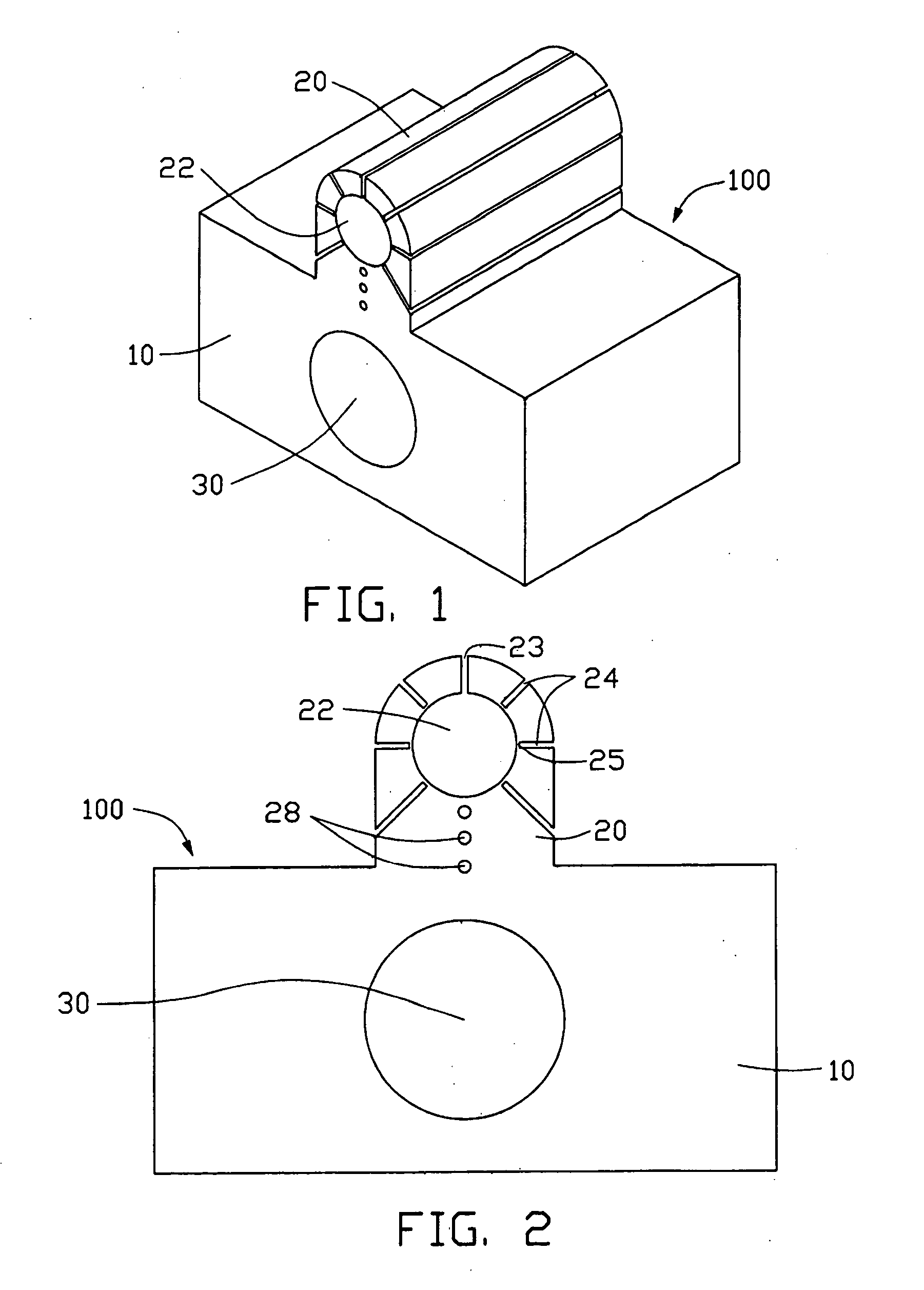
[0012]FIGS. 1-2 show a platform 100 of a measuring device for a heat pipe in accordance with a preferred embodiment of the present invention. The platform 100 comprises a base 10 and a clip-like mechanism 20 integrally extending from the base 10.

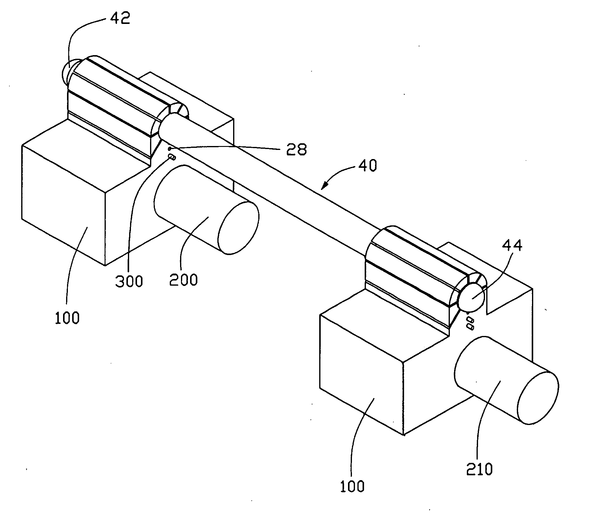
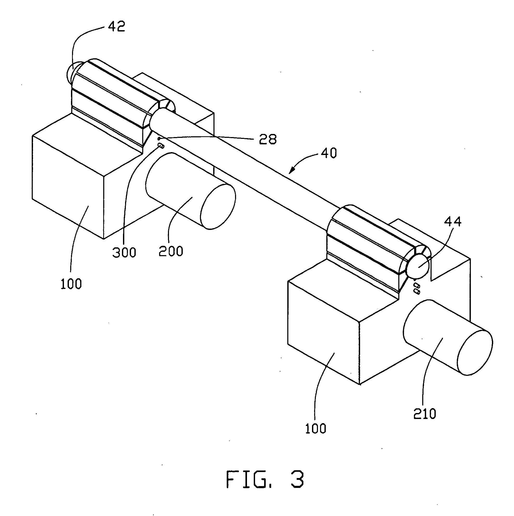
[0013] The base 10 defines a hole 30 therein. The hole 30 is for receiving a heating member 200 (see FIG. 3) such as a heating tube, or a cooling member 210 (see FIG. 3) such as a cold water pipe as a temperature adjusting member.

[0014] The clip 20 defines a substantially central aperture 22 for receiving one part of a pipe-like member like a heat pipe 40 (see FIG. 3). A split 23 is defined in the clip 20 from its outer surface, in communicating with the aperture 22. Thus the clip 20 is a little elastic. A plurality of grooves 24 is radially defined in the clip 20. The clip 20 further defines a plurality of thin partitions 25 interposed between the aperture 22 and the grooves 24. The thin partitions 25 may be manufactured by precision wire...


PUM

PropertyMeasurementUnit
temperaturesaaaaaaaaaa
temperatureaaaaaaaaaa
sizeaaaaaaaaaa

Abstract

A measuring device for a heat pipe (40) includes a first platform (100), a second platform (100), a heating member (200), a cooling member (210) and thermal probes (300). The heat pipe (40) includes a first end (42) and a second end (44) opposite to the first end (42). The first platform (100) flexibly receives the first end (42) of the heat pipe (40) therein and the second platform (100) flexibly receives the second end (44) of the heat pipe (40) therein. The heating member (200) is for heating the first end (42) of the heat pipe (40) and the cooling member (210) is for cooling the second end (44) of the heat pipe (40). The thermal probes (300) are received into the first platform (100) and the second platform (100) to measure the temperatures where they are positioned.

Description

TECHNICAL FIELD [0001] The present invention relates to a measuring device for a heat pipe, and particularly to a measuring device which can accurately measure heat transfer characteristics of the heat pipe. BACKGROUND [0002] Heat pipes have been suggested for cooling electronic components. Conventionally, a heat pipe comprises an evaporator to take in heat and a condenser to expel heat. Working fluid is contained in the heat pipe to transfer heat from the evaporator to the condenser. The heat entering the evaporator of the heat pipe boils the fluid and turns it into a vapor. The vapor expands in volume and travels to the condenser where it condenses to a liquid and gives up its heat. The liquid is then returned to the evaporator by gravity or a wick and starts the process again. [0003] However, a heat pipe has its limits such as capillary pumping limit, nucleate boiling limit and entrainment limit. Measuring devices can measure heat transfer characteristics of the heat pipe which d...

Claims


Application Information

Patent Timeline
Patent Type & Authority Applications(United States)
IPC IPC(8): G01K1/14F28D15/02G01K7/02G01K13/00G01N25/18
CPCG01K1/143F28F2200/005
Inventor CHIEN, YANG-CHANG
Owner HON HAI PRECISION IND CO LTD
Why Eureka
Try Eureka