
Timing adjustment method and digital filter and receiver using the method

a technology of digital filters and adjustment methods, applied in pulse manipulation, pulse technique, synchronisation signal speed/phase control, etc., can solve the problem of increasing the number of taps constituting the fir digital filter, and achieve the effect of preventing an increase in the circuit scale and fast sampling ra

Inactive Publication Date: 2005-10-06
SANYO ELECTRIC CO LTD
View PDF10 Cites 9 Cited by
  • Summary
  • Abstract
  • Description
  • Claims
  • Application Information

AI Technical Summary

Benefits of technology

[0009] The present invention has been done in view of the aforementioned circumstances and its object is to provide a timing adjustment method which enables timing adjustment at a fast sampling rate and also prevents an increase in the circuit scale. Further, the invention relates to a digital filter and a receiver that uses the inventive method.
[0011] In the filter described above, adjustment of timing of sampling of added data is not performed after increasing the sampling rate of the input data. Instead, timing adjustment is performed by retaining a plurality of types of coefficients to be multiplied by the input data and selecting one of the coefficients in accordance with required timing. This makes it possible to prevent an increase in the number of taps and an increase in the circuit scale, while enabling high-precision timing adjustment.

Problems solved by technology

These processes result in an increase in the number of taps constituting the FIR digital filter.

Method used


Image

  • Timing adjustment method and digital filter and receiver using the method
  • Timing adjustment method and digital filter and receiver using the method
  • Timing adjustment method and digital filter and receiver using the method

Examples


Embodiment Construction

[0039] The invention will now be described based on the following embodiments which do not intend to limit the scope of the present invention but exemplify the invention. All of the features and the combinations thereof described in the embodiments are not necessarily essential to the invention.

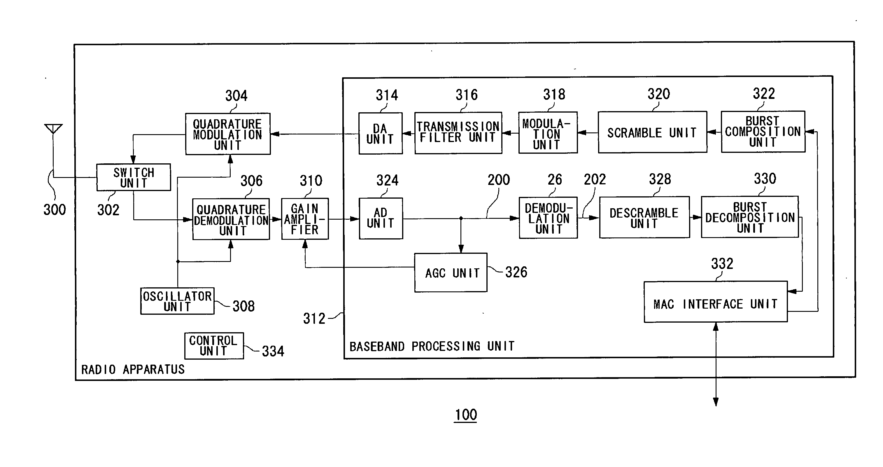
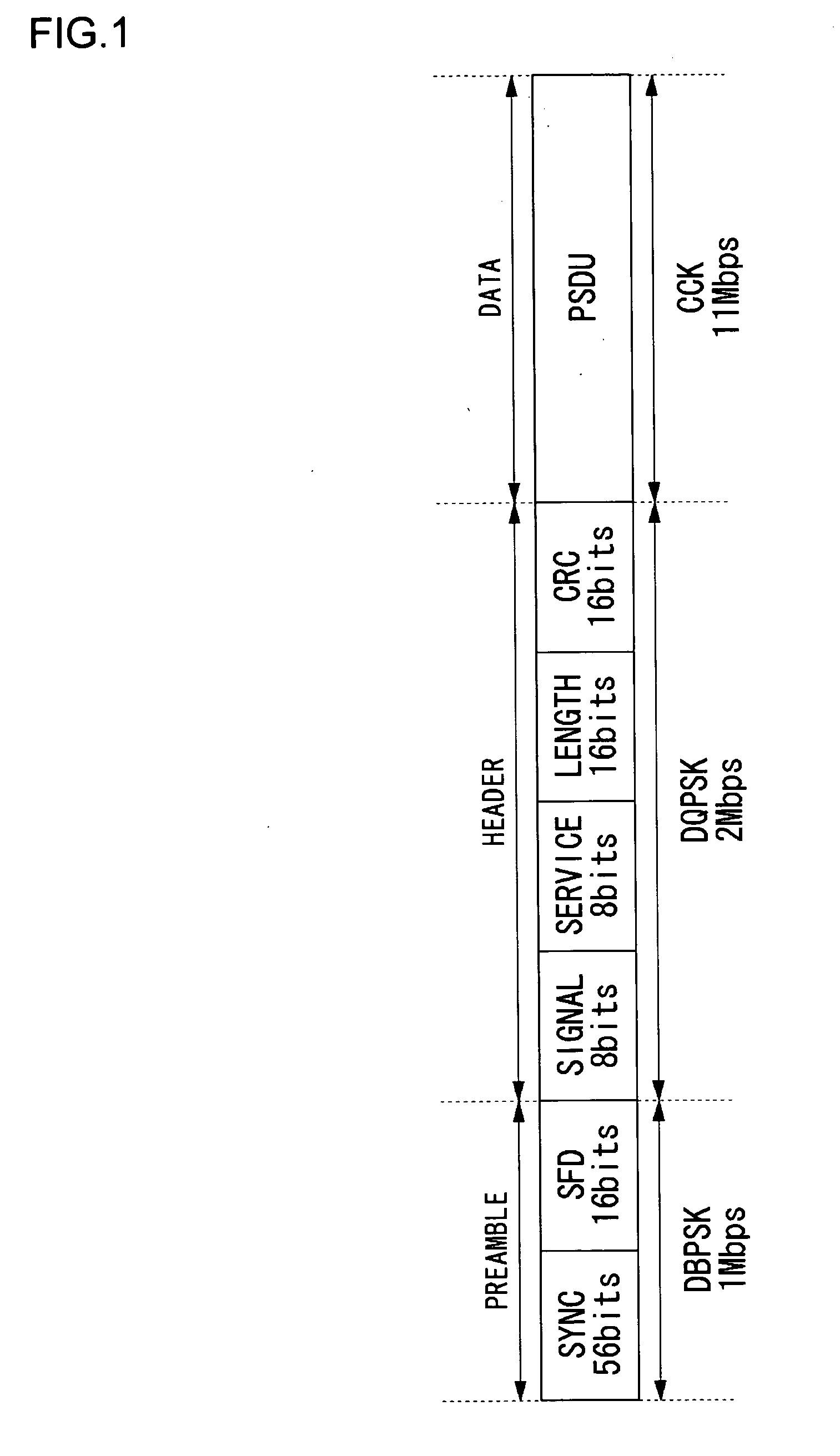
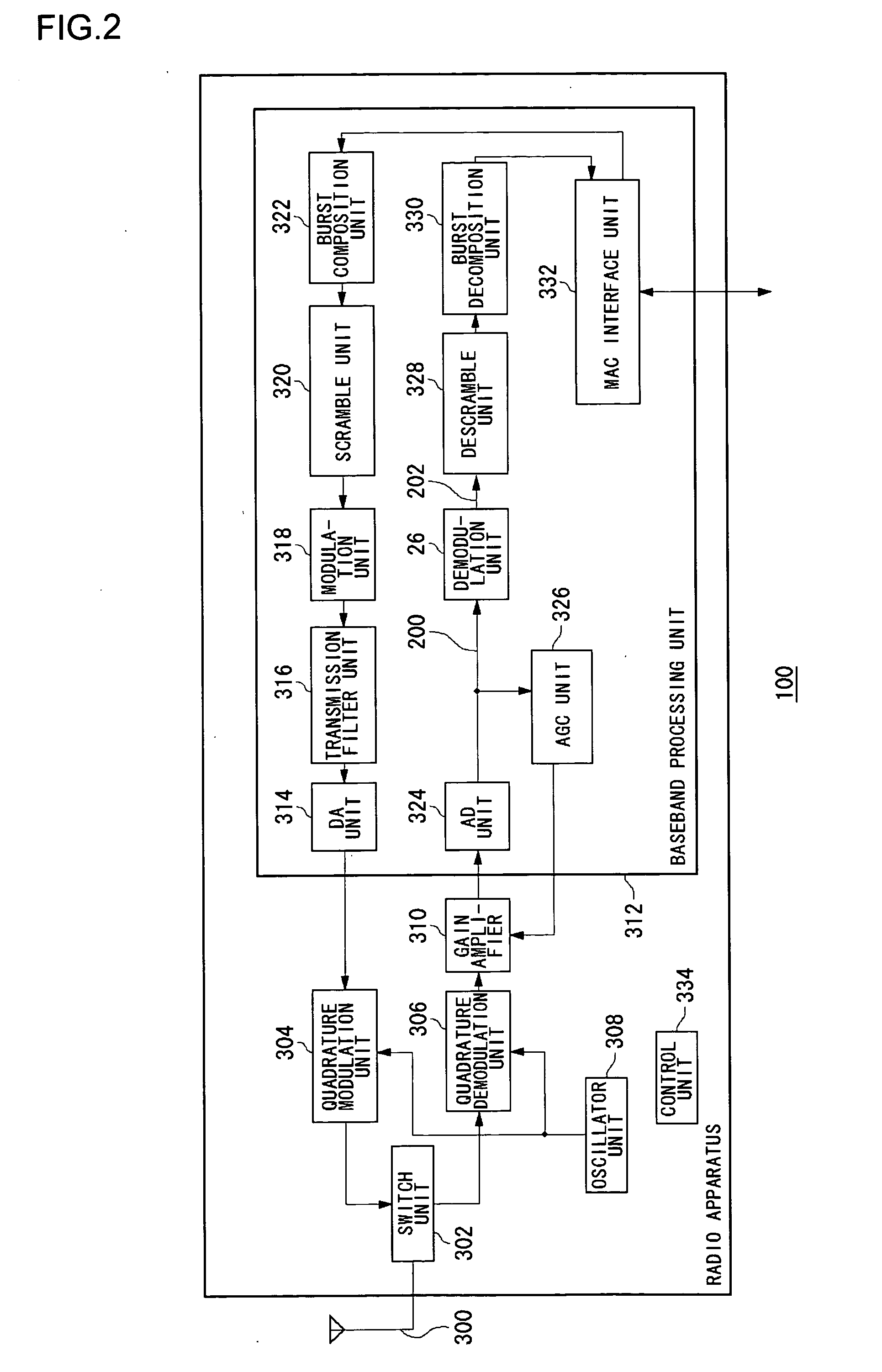
[0040] Before giving a specific description of the present invention, a summary of will be given. An example of the present invention relates to a wireless LAN apparatus, and particularly, to a receiver that complies with the IEEE 802.11b standard. The receiver subjects a received CCK modulated signal to fast Fourier transform (FWT) computation. The receiver further selects the largest correlation from a plurality of correlations obtained as a result of FWT computation and reconstructs a combination of phase signals corresponding to the largest correlation thus selected. Since a CCK modulated signal is generated based on differentially encoded signals, a receiver normally does not require co...


PUM


Abstract

A delay unit comprises a plurality of taps for sequentially delaying an input digital received signal. A shift unit changes combinations of a plurality of digital received signals delayed by the delay unit and a multiplier unit. A coefficient retaining unit manages a plurality of coefficients to be multiplied by the plurality of digital received signals delayed by the delay unit. A selector unit 352 selects one of the coefficients retained in the coefficient retaining unit in accordance with an instruction from a control unit. The multiplier unit multiplies the plurality of digital received signals delayed by the delay unit by the coefficient selected by the selector unit. An adder adds up results of multiplication by the multiplier unit and outputs a result of addition as a filter output signal.

Description

BACKGROUND OF THE INVENTION [0001] 1. Field of the Invention [0002] The present invention relates to a timing adjustment technology and, more particularly, to a timing adjustment method for adjusting the timing of an input signal and outputting the time-adjusted signal. The invention further relates to a digital filter and a receiver using the method. [0003] 2. Description of the Related Art [0004] Wireless local area network (LAN) that complies with the IEEE 802.11b standard is practiced as a spread spectrum communications system using a radio frequency of 2.4 GHz band. The IEEE 802.11b wireless LAN enables a maximum transmission rate of 11 Mbps using complementary code keying (CCK). In a receiver adapted for CCK modulation, a plurality of waveform patterns for a transmitted signal are generally prepared. A combination of signals having a waveform that best matches the waveform of the received signal is defined as a demodulation result (See reference (1) in the following Related Ar...

Claims


Application Information

Patent Timeline
Patent Type & Authority Applications(United States)
IPC IPC(8): H03H17/08H03H17/02H03H17/06H03K5/159H04B1/707H04B1/7093H04J11/00H04L7/02H04L7/04
CPCH04B1/7093H04B2001/70935H04L7/042H04L7/0029H04J13/0074
Inventor KOHYAMA, TADAHISA
Owner SANYO ELECTRIC CO LTD
Learn More