Baseband module and data transmission method

Inactive Publication Date: 2005-10-06
WSOU INVESTMENTS LLC
View PDF5 Cites 2 Cited by
  • Summary
  • Abstract
  • Description
  • Claims
  • Application Information

AI Technical Summary

Benefits of technology

[0007] It is thus one object of the present inventi

Problems solved by technology

Increased demand and availability of mobile Internet services will create challenges for network operators and service providers due to the rising cost of the infrastructure.
The star topology has the

Method used


Image

  • Baseband module and data transmission method
  • Baseband module and data transmission method
  • Baseband module and data transmission method

Examples


Embodiment Construction

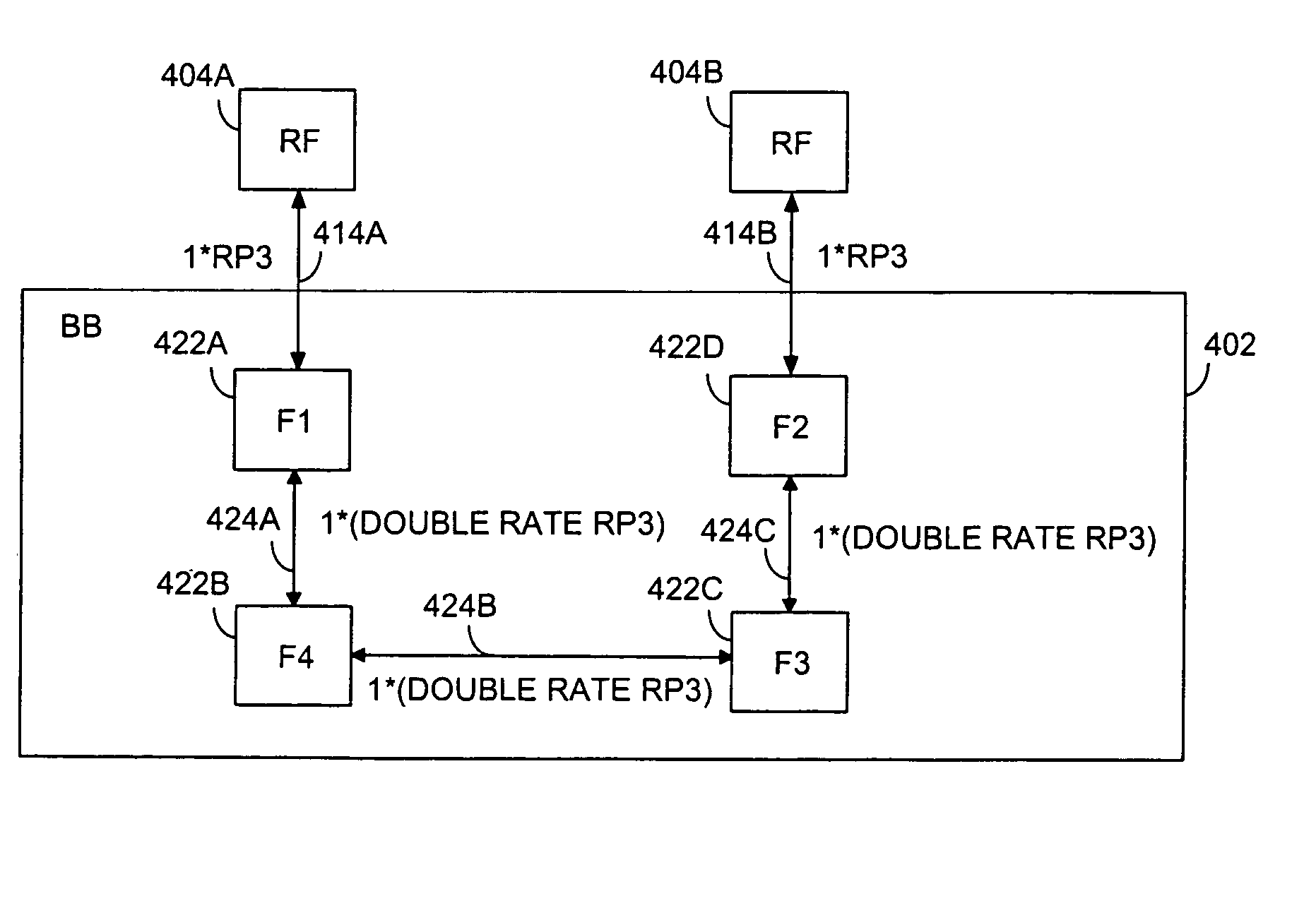
[0028]FIG. 4A shows one embodiment of a topology according to the invention. In FIG. 4A, the baseband devices 422A to 422D within a baseband module 402 are arranged in a chain so that the baseband devices F3 and F4 in the middle of the chain have an interface with two other baseband devices. F3, for instance, has internal interfaces 424B and 424C to F2 and F4. The baseband devices at the end of the chain, that is, devices F1 and F2 have one internal interface and one external interface. F1, for instance, has an internal interface 424A with baseband device F4 and an external interface 414A with RF module 404A.

[0029] In FIG. 4A, the baseband processing capacity of the baseband module is 2+2 meaning that there are two carrier waves and two sectors to be served. Each carrier wave is transmitted / received by two antennas whereby the baseband module 402 shall be capable of handling 8 duplex data streams. Therefore, the baseband module has two external RP3 sub-interfaces, each of the sub-i...


PUM


Abstract

A baseband module for a base station is in a mobile communication network. The baseband module includes at least two baseband devices connected to each other by an internal interface, thereby forming a chain of baseband devices. The baseband module is connected to a radio frequency module by two external interfaces, each external interface being connected to a baseband device at the end of the chain of baseband devices.

Description

FIELD OF THE INVENTION [0001] The invention relates to a baseband module suitable to be used in a radio network element, such as a base station within a mobile network. BACKGROUND OF THE INVENTION [0002] Increased demand and availability of mobile Internet services will create challenges for network operators and service providers due to the rising cost of the infrastructure. Large number of base transceiver stations (BTS) are needed to support the new technologies and to satisfy the capacity demand of the advanced services. [0003] The Open Base Station Architecture Initiative (OBSAI) is an organization that aims to create a set of open specifications for the base station architecture. OBSAI has defined a modular base station architecture and detailed specifications for the interfaces between the modules. This architecture is depicted in FIG. 1. The base station in FIG. 1 includes a transport module 100 providing adaptation between external network interfaces and standard BTS intern...

Claims


Application Information

Patent Timeline
IPC IPC(8): H04BH04W88/08
CPCH04W88/08H04B7/155
Inventor VAINIKKA, MARKKUKINNUNEN, HARRI
Owner WSOU INVESTMENTS LLC
Why Eureka
Try Eureka