
Pressure vibration generator

Inactive Publication Date: 2005-10-13
JAPAN AEROSPACE EXPLORATION AGENCY +1
View PDF14 Cites 1 Cited by
  • Summary
  • Abstract
  • Description
  • Claims
  • Application Information

AI Technical Summary

Benefits of technology

[0004] A main object of the present invention is to provide a pressure oscillation generator enabling further size reduction.
[0006] In the pressure oscillation generator according to the present invention as described above, when the heat input section is sufficiently heated, self-excited vibration is generated in the work transfer tube, and the resonator provided on the work output side of the work transfer tube resonates. In this state, when a work (pressure wave) is inputted from the work generating section to the heat removal section of the heat exchanger, the work is amplified via the heat exchanger, transferred to the work transfer tube, and outputted to the output section. Namely, the pressure oscillation generator also functions as an amplifier. As the work outputted in the amplified state is larger than the inputted work, by using a portion of the outputted work as energy for driving the work generating section, the pressure oscillation generator can continuously be driven only by heating, and without using electric energy or the like. Therefore when the pressure oscillation generator is used for supplying pressure oscillation to a pulse tube refrigerator or the like mounted in a satellite, it is required to provide the heat input section so that the heat input section is directly heated by the solar heat or the like, and it is not required to use a large scale solar system for converting the thermal energy as described above to electric energy, so that the size reduction of the pressure oscillation generator can further be promoted.
[0008] With the configuration as described above, as the work output side of the work transfer tube and the work generating section are communicated to each other via the return section, so long as the heat input section is heated, also the work generating section is continuously driven in the self-excited state by a portion of the work outputted from the work transfer tube, and even a switch mechanism for starting driving and the like are not required in the pressure oscillation generator, so that the configuration is further simplified and further size reduction of the pressure oscillation generator is possible.
[0011] In contrast, as the solid displacer is vibrated within the accommodation body, the length can be minimized so long as a required amplitude of the solid displacer can be insured so that the size reduction is secured.

Problems solved by technology

In the conventional types of solar systems, however, as the conversion efficiency from thermal energy to electric energy is extremely low, it is required to use solar panels or the like with very large size for obtaining sufficient electric energy, which causes various troubles when mounted on a satellite.

Method used


Image

  • Pressure vibration generator
  • Pressure vibration generator

Examples


Embodiment Construction

[0015] An embodiment of the present invention is described below with reference to the related drawing.

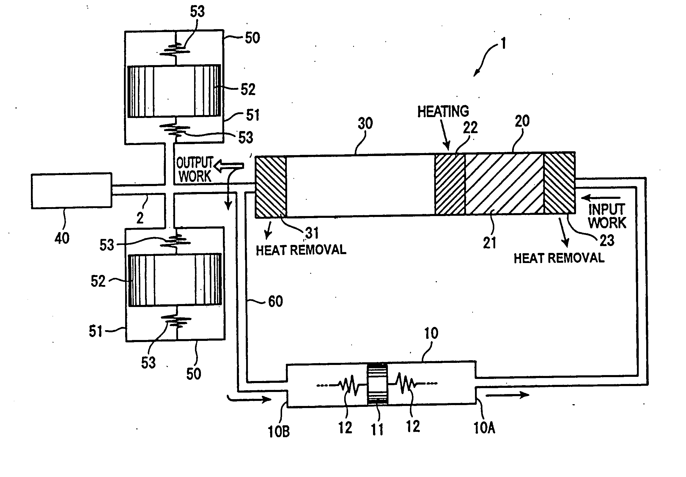
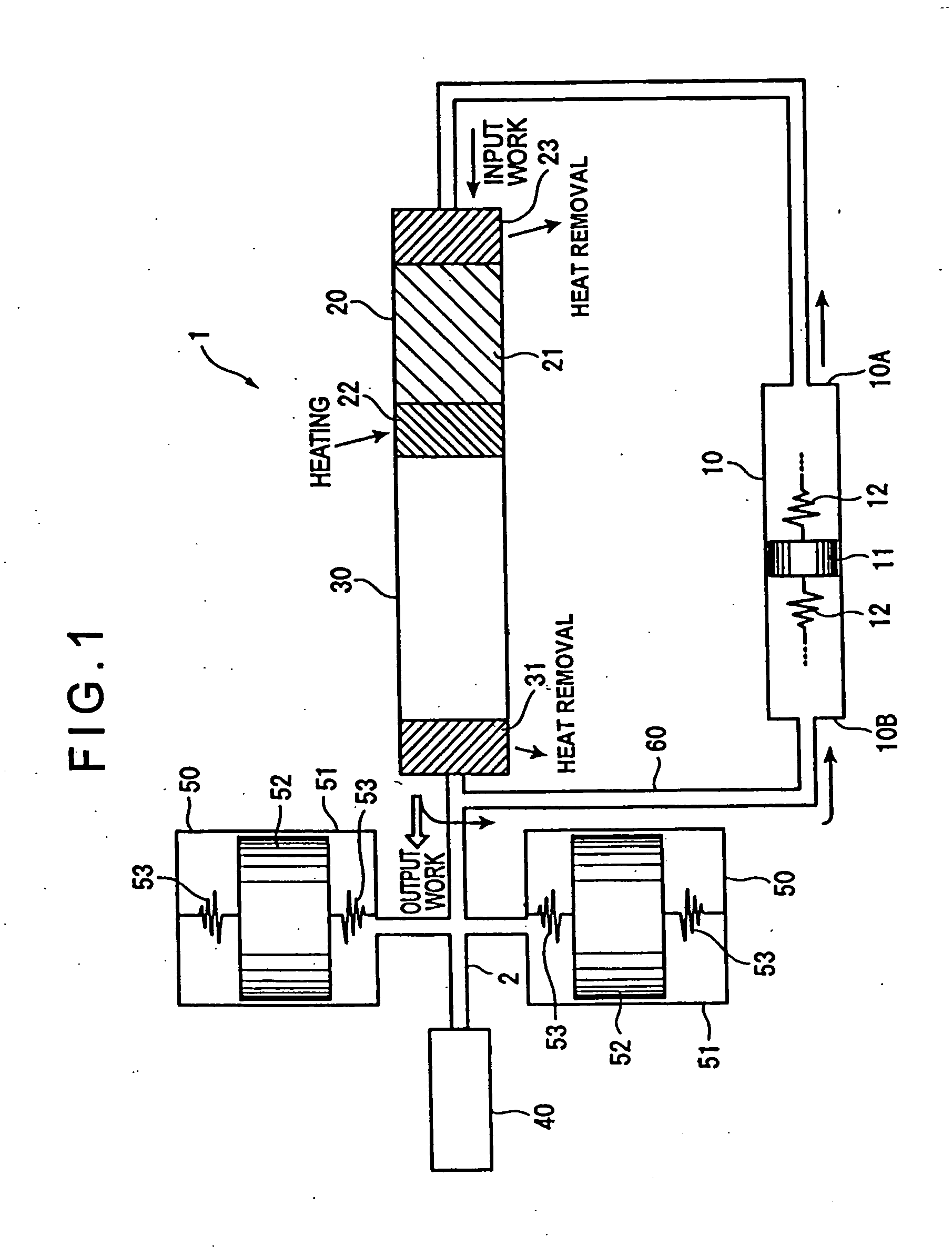
[0016]FIG. 1 is a schematic view showing a pressure oscillation generator 1 according to the embodiment of the present invention.

[0017] The pressure oscillation generator 1 is a device for generating pressure oscillation in a working medium such as helium in a system, and is advantageously used for supplying the pressure oscillation to a pulse tube refrigerator mounted, for instance, on a satellite.

[0018] More specifically, the pressure oscillation generator 1 comprises a cylinder (work generating section) 10 for generating a pressure wave with a prespecified magnitude as an input work from a generating section 10A, a heat exchanger 20 receiving a work from the cylinder 10 at one edge thereof and outputting the work from the other edge thereof, a work transfer tube 30 connected to the output side of the heat exchanger 20, an output section 40 provided in the output side of the w...


PUM


Abstract

In the pressure oscillation generator 1, self-excited vibration is generated in a work transfer tube 30 by heating a heat input section 22 and also a resonator 50 is resonated, and when a work is inputted into a heat exchanger 20, the work is amplified by the heat exchanger 20, and is transferred to the heat transfer tube 30 and is then outputted to an output section 40. Because of the configuration, an outputted work can be amplified to a work larger than the inputted work, so that, by using a portion of the outputted work as energy for driving the cylinder 10, the pressure oscillation generator 1 can continuously be driven only by heating and without using electric energy generated by a large scale solar system or the like, which enables substantial size reduction of the pressure oscillation generator 1.

Description

TECHNICAL FIELD [0001] The present invention relates to a pressure oscillation generator (pressure vibration generator), and more specifically, to a pressure oscillation generator used for supplying pressure oscillation to, for instance, a pulse tube refrigerator. BACKGROUND ART [0002] Recently researches are very active in examining the possibility of mounting a refrigerating machine such as a pulse tube (cryo) refrigerator or the like in a satellite for cooling various types of components and devices in the satellite. The pulse tube refrigerator functions by supplying pressure oscillation to a pulse tube, and as the pressure oscillation generator for generating vibration pressure, there have been proposed those using electric energy, or more specifically those each comprising a compressor driven by an electric motor and an electronically controlled switch valve provided therein. In this case, a large size solar system for converting thermal energy from the Sun to electric energy i...

Claims


Application Information

Patent Timeline
IPC IPC(8): F02G1/043F25B9/14F01B11/08
CPCF25B9/14F25B9/145F25B2309/1403F25B2309/1411F25B2309/1426
Inventor MATSUBARA, YOICHITOHYAMA, SHINICHISUGITA, HIROYUKI
Owner JAPAN AEROSPACE EXPLORATION AGENCY
Features
  • Generate Ideas
  • Intellectual Property
  • Life Sciences
  • Materials
  • Tech Scout
  • Unparalleled Data Quality
  • Higher Quality Content
  • 60% Fewer Hallucinations
Learn More