
Inline automatic/manual shifter

a shifter and automatic technology, applied in the direction of manual control with single controlling member, mechanical control devices, instruments, etc., can solve the problems of complex structure and increase the cost of manufacturing the shifting arrangement, and achieve the effect of increasing the cost of manufacturing

Inactive Publication Date: 2005-10-13
NISSAN TECHN CENT NORTH AMERICA
View PDF11 Cites 24 Cited by
  • Summary
  • Abstract
  • Description
  • Claims
  • Application Information

AI Technical Summary

Benefits of technology

[0006] It has been discovered that with most conventional shifting arrangement that requires two parallel shifting paths, the driver sometimes has a difficulty in moving the shift lever in a lateral direction to change from an automatic shift mode “D” to a manual shift mode “M”. Moreover, additional structure must often be provided for the shift lever to move in a lateral direction from the automatic shift mode “D” to the manual shift mode “M”. This

Problems solved by technology

This additional structure can increase the cost for manufacturing the shifting arrangement.
In addition, some conventional shifting arrangements require complex structures to change from the automatic shift mode “D” to the manual shift mode “M”.

Method used


Image

  • Inline automatic/manual shifter
  • Inline automatic/manual shifter
  • Inline automatic/manual shifter

Examples


Embodiment Construction

[0028] Selected embodiments of the present invention will now be explained with reference to the drawings. It will be apparent to those skilled in the art from this disclosure that the following descriptions of the embodiments of the present invention are provided for illustration only and not for the purpose of limiting the invention as defined by the appended claims and their equivalents.

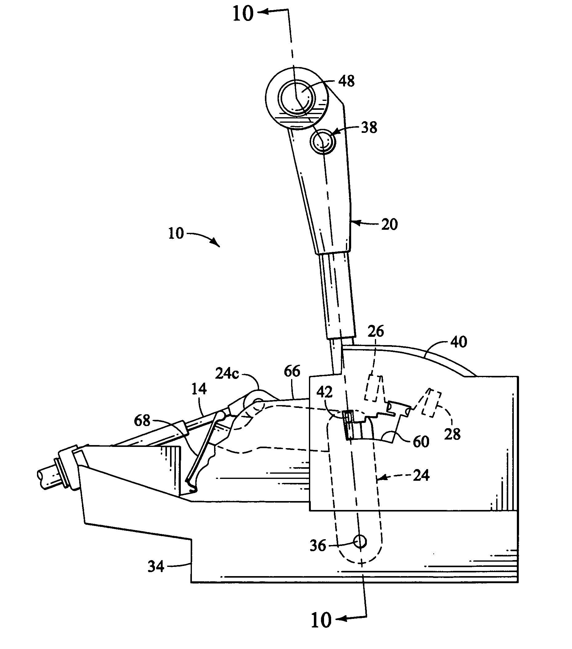
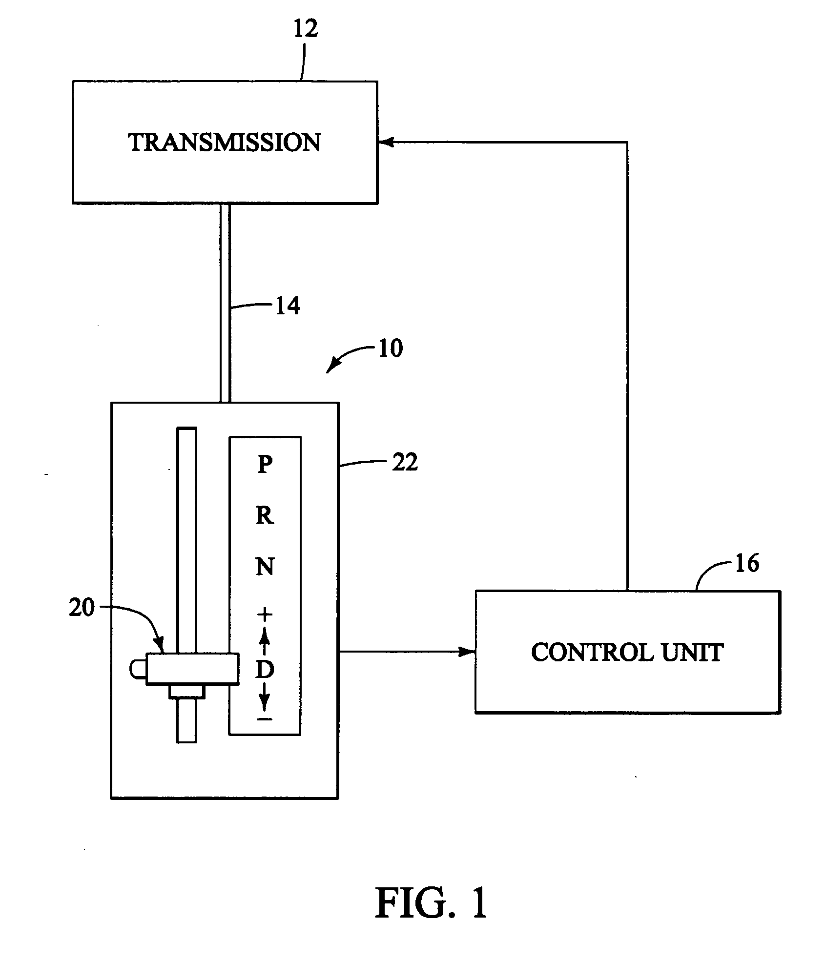
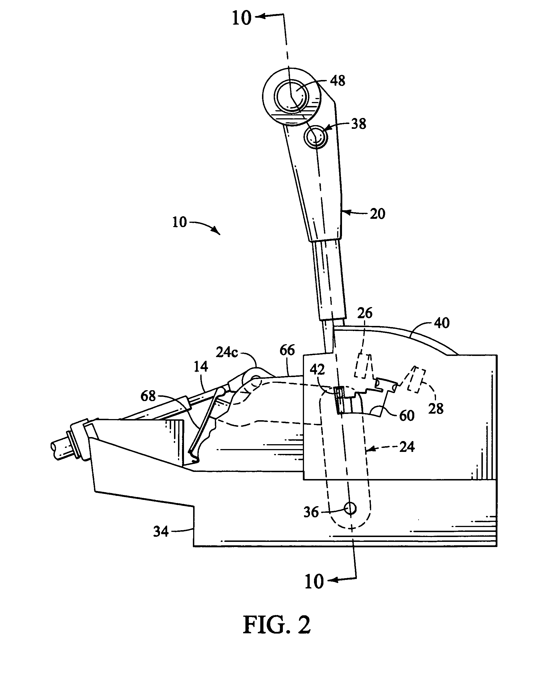
[0029] Referring initially to FIG. 1, an inline automatic / manual shifter 10 is illustrated in accordance with a preferred embodiment of the present invention. Basically, the inline automatic / manual shifter 10 is mechanically coupled to an automatic transmission 12 by a shifter movement transmitting element 14 such as an automatic transmission cable and / or linkage assembly. Also, the inline automatic / manual shifter 10 is electrically coupled to a control unit 16 for manually changing the gear ratio of the automatic transmission 12. The control unit 16 preferably includes a microprocessor with an a...


PUM


Abstract

An inline automatic / manual shifter is provided with a shift lever that moves in a straight line path to select one of a shift position. Manual up-shift and down-shift switches are actuated by the shift lever while in the drive position to cause an upshift or a downshift of the automatic transmission. The shift position retaining mechanism includes a detent spring engages notches in a detent plate to hold the shift lever in one of the shift positions. A drive position notch has an up-shift switch ramp surface and a down-shift switch ramp surface with a center neutral drive location located between the up-shift and down-shift switch ramp surfaces. The up-shift and down-shift switch ramp surfaces are arranged such that the detent spring applies an urging force on the drive position notch to bias the detent spring and the shift lever to the center neutral drive location.

Description

BACKGROUND OF THE INVENTION [0001] 1. Field of the Invention [0002] The present invention generally relates to an inline automatic / manual shifter. More specifically, the present invention relates to a shifter for an automatic transmission that includes a manual shift mode lying with the same shifting plane as the automatic shift mode. [0003] 2. Background Information [0004] Typically, automotive vehicles having an automatic transmission have a shifter for selecting a gear position such as a park position “P”, a reverse position “R”, a neutral position “N” and a drive position “D”. However, more recently, vehicles with automatic transmissions have been developed that allow the driver to manually change the gear ratio of the transmission. A variety of shifting arrangements have been developed to accomplish both the automatic shift mode and the manual shift mode. One of the most common methods is to utilize a shifter with a shift lever that has an automatic shifting path and a manual s...

Claims


Application Information

Patent Timeline
IPC IPC(8): F16H59/02F16H59/10B60K20/00
CPCF16H59/0204F16H59/10F16H2059/0239F16H2059/0282Y10T74/20067
Inventor OTSUKA, HIROYUKI
Owner NISSAN TECHN CENT NORTH AMERICA
Learn More