Vehicle power transmission system

a transmission system and power transmission technology, applied in the direction of control devices, vehicle components, auxilary drives, etc., can solve the problems of increasing intrusive noise, increasing the cost, and increasing the cost, so as to reduce the lateral dead space in the vehicle body, reduce the lateral width of the space for laterally offsetting the first part from the prime mover, and improve the suspension

Inactive Publication Date: 2005-10-13
KANZAKI KOKYUKOKI MFG
View PDF4 Cites 16 Cited by
  • Summary
  • Abstract
  • Description
  • Claims
  • Application Information

AI Technical Summary

Benefits of technology

[0028] In association with the transmission direction changing part having the universal joint, preferably, the vehicle body frame comprises: a first frame part supporting the leading part; and a second frame part supporting the ending part. The second frame part is pivotally connected to the first frame part through a pivot. An axis of the pivot passes through a center of the universal joint of the transmission direction changing part, thereby providing advantage in suspension of wheels for a vehicle.
[0029] In association with the arrangement of the transmission direction changing part, alternatively, preferably, when viewed in plan, a first part of the power take-off train from the leading part to the transmission direction changing part and a second part of the power take-off train from the transmission direction changing part to the ending part are extended in a substantially fore-and-aft

Problems solved by technology

Therefore, the first transaxle is complicated and expanded laterally, thereby increasing the cost.
However, if the drive train is disposed below the prime mover, the vehicle may have insufficient ground clearance.
Accordingly,

Method used


Image

  • Vehicle power transmission system
  • Vehicle power transmission system
  • Vehicle power transmission system

Examples


second embodiment

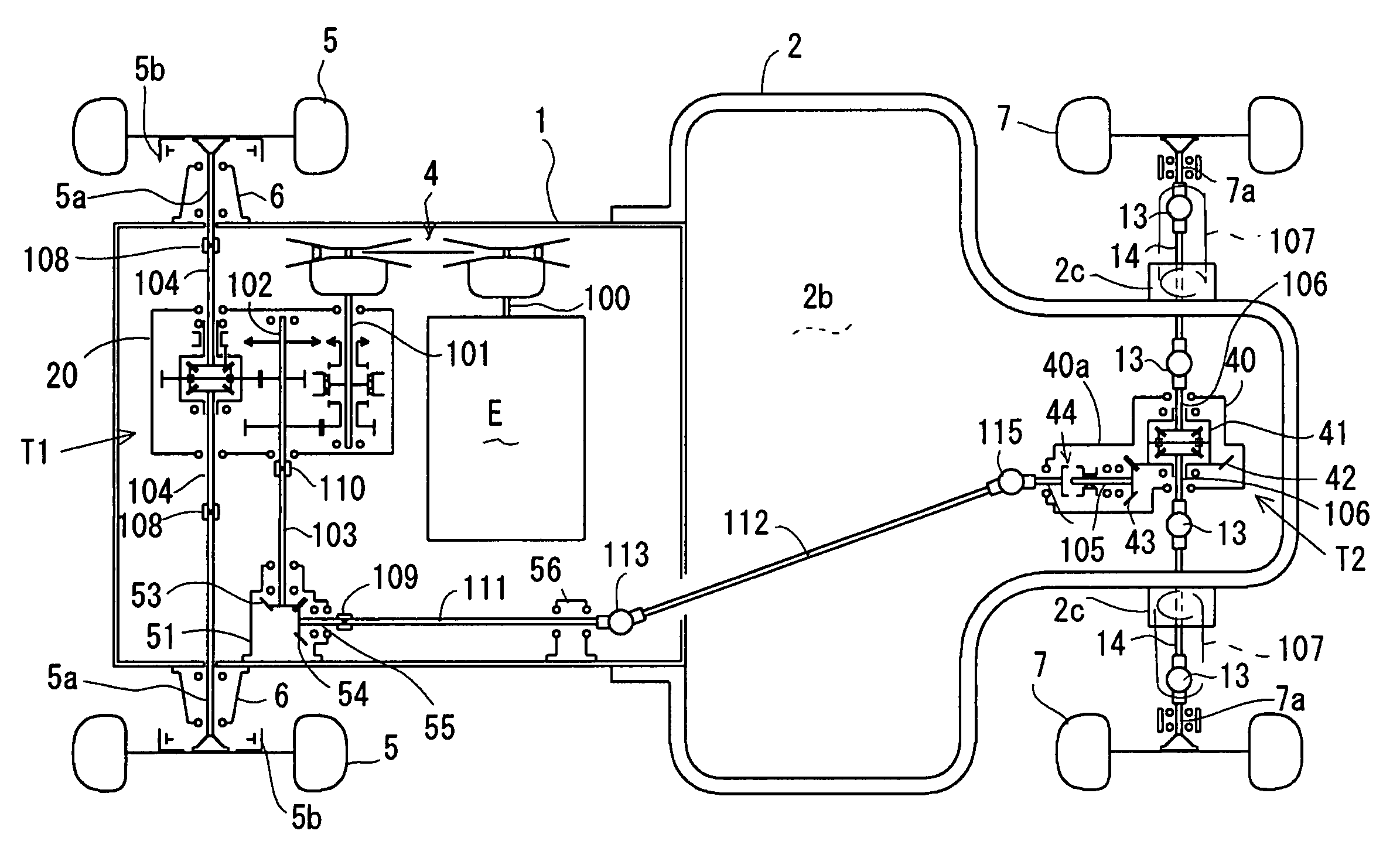
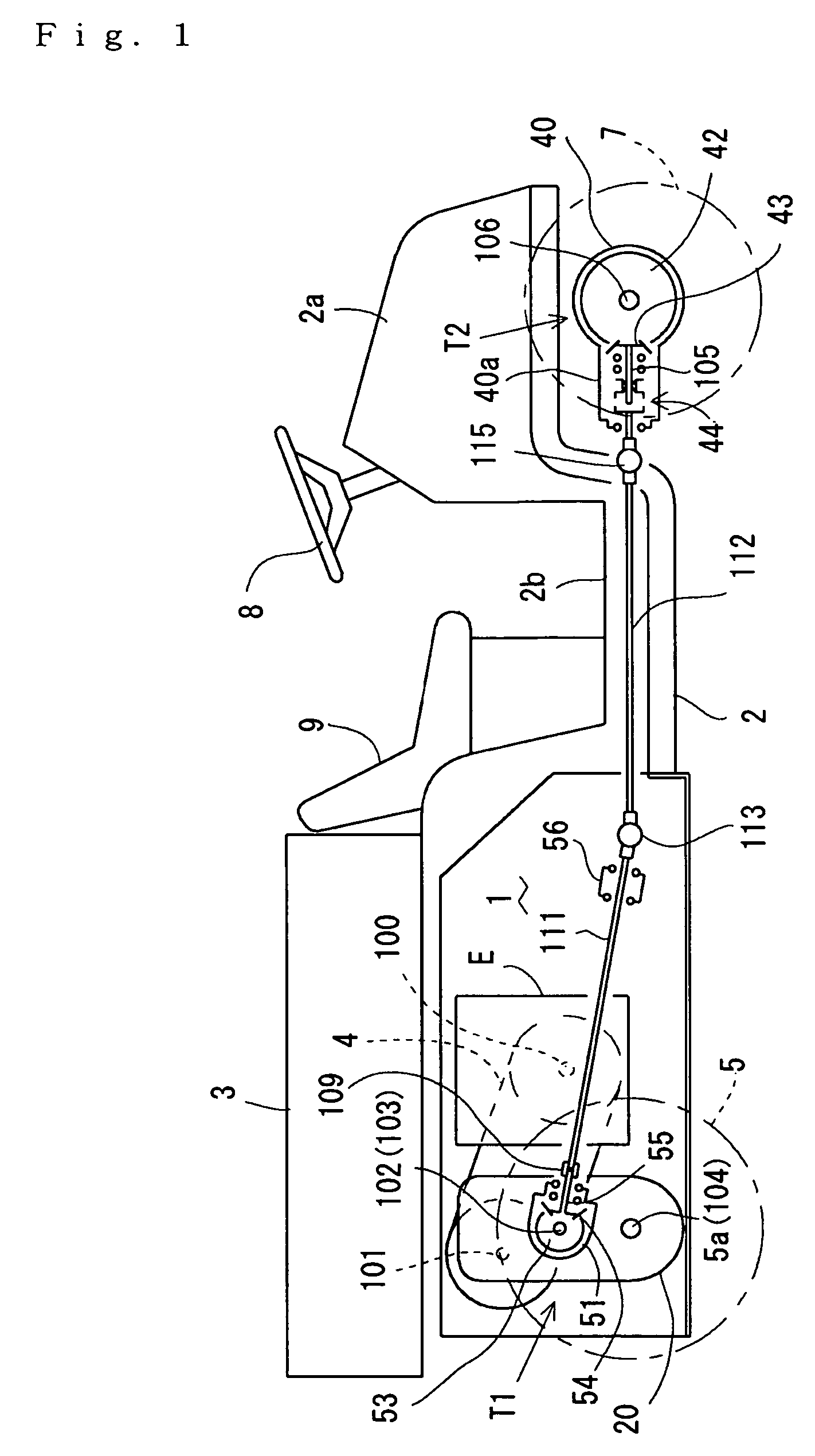
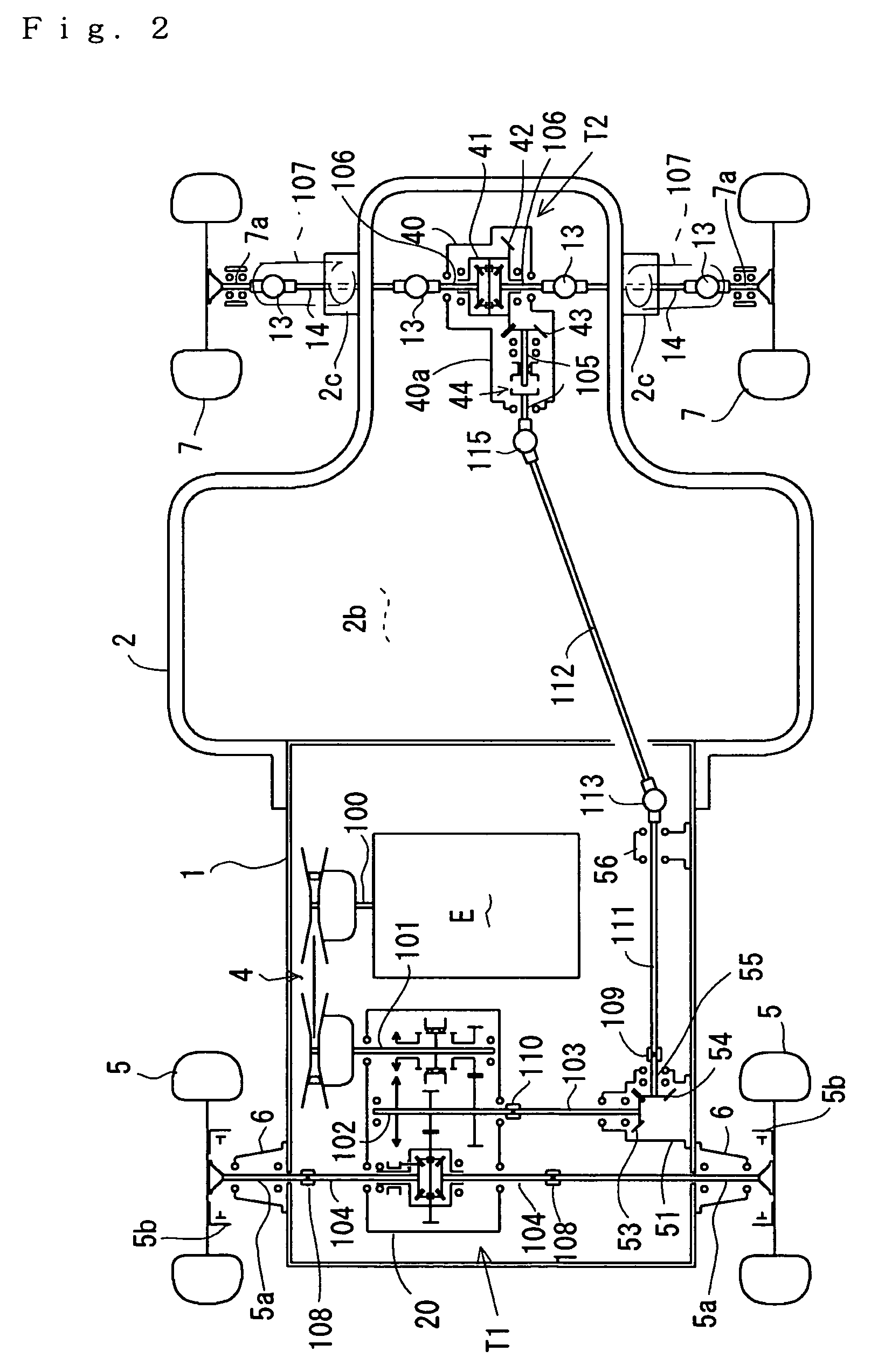
[0073] A footboard is laid on the rear half of the front frame 2 behind the rear end of the front cover 2a so as to form a horizontal platform 2b (however, in a later-discussed second embodiment shown in FIGS. 4 and 5, the platform 2b has a slant portion above a later-discussed power take-off system). As clearly shown in FIG. 2, the platform 2b is extended laterally outward. An operator's seat 9 is provided upright on the rear end of the front frame 2 (just before the rear frame 1 and the cargo deck 3), and the platform 2b is extended leftward, rightward and forward from the seat 9.

[0074] Explanation will be given of the structure of the rear transaxle T1 especially according to FIG. 3. In the vehicle, the rear transaxle T1 has a housing 20 whose bottom end is fixed onto the bottom surface of the rear frame 1 by bolting. The housing 20 pivotally supports the input shaft 101 at an upper part thereof, the left and right axles 104 at the lower part thereof, and an intermediate transmis...

first embodiment

[0096] In the power take-off train of this embodiment, propeller shafts 121 and 122 are coaxially linearly extended leftward slantwise from the leading part disposed near the right end of the rear portion of the vehicle to the front transaxle T2 disposed at the substantial lateral center of the vehicle (the front transaxle T2 has the same construction and arrangement as the first embodiment). Namely, this power take-off train does not have the transmission direction changing part, equivalent to the universal joint 113, disposed at substantially the same height as the ending part (the universal joint 115) to the front transaxle T2. The part of the power take-off train to be disposed below the platform 2b is also slant. The platform 2b is formed to have a slant part so as to pass the slant part of the power take-off train therebelow, thereby reducing an operation portion above the platform 2b. Also, the lateral width of a space for passing the power take-off train on the right side of...

fifth embodiment

[0104] In consideration of the differential gear mechanism 72 disposed near the right end of the vehicle, the left axle 131 may be a single shaft, which is longer than the right axle 131 and extended to the left middle wheel 10. Alternatively, the left axle 131 may be divided at the middle thereof into divisional parts, which are connected by spline-fitting through a coupling, similar to the sleeve coupling 108. The same may be said of the later-discussed

[0105] A bull gear 73 of the differential gear mechanism 72 is a bevel gear, which engages with a bevel gear 74 fixed onto the front end of the propeller shaft 132. The bevel bull gear 73 engages at a front end thereof with a bevel gear 75 fixed onto a rear end of a propeller shaft 133. The propeller shaft 133 is extended in the fore-and-aft direction when viewed in plan, forward from the transmission housing 71, and is connected to the universal joint 113. The universal joint 113 is disposed just before the transmission housing 71 ...


PUM


Abstract

A vehicle power transmission system comprises: a prime mover mounted on a vehicle body frame; a first axle and a first transaxle for driving the first axle disposed at one of front and rear portions of a vehicle, the first transaxle having a first input part projecting outward therefrom, and the first transaxle having a power take-off shaft projecting outward therefrom opposite to the first input part; a speed-changing transmission drivingly interposed between the prime mover and the first input part; a second axle and a second transaxle for driving the second axle disposed at the other rear or front portion of the vehicle, the second axle having a second input part; and a power take-off train extended from a leading part to an ending part. The prime mover is disposed between the first transaxle and the second transaxle in a fore-and-aft direction of the vehicle. The leading part of the power take-off train is drivingly connected to the power take-off shaft, and the ending part of the power take-off train is drivingly connected to the second input part. The leading part of the power take-off train is separated from the first transaxle and laterally offset from the prime mover.

Description

BACKGROUND OF THE INVENTION [0001] 1. Field of the Invention [0002] The present invention relates to a power transmission system for a vehicle, such as a cart, having front and rear transaxles and a prime mover disposed between the transaxles, wherein the power transmission system includes a power take-off from one of the front and rear transaxles, which is driven by the prime mover, and transmits the power to the other transaxle. [0003] 2. Related Art [0004] Conventionally, there is a well known vehicle comprising a first transaxle for driving a first axle and a second transaxle for driving a second axle, the first and second transaxles being distributed before and behind a prime mover, such as an internal combustion engine, supported by a vehicle body frame. An input part of the first transaxle is disposed on one of left and right sides of the first transaxle so as to be drivingly connected to the prime mover through a transmission such as a continuously variable transmission (CVT...

Claims


Application Information

Patent Timeline
IPC IPC(8): B60K17/08B60K17/22B60K17/28B60K17/34B60K17/342
CPCB60K17/08B60K17/22B60K17/28B60K17/34B60K17/342
Inventor IMA, AKIHIROHASEGAWA, TOSHIYUKIOHTSUKI, KAZUHIKOYASUI, KENICHI
Owner KANZAKI KOKYUKOKI MFG
Why Eureka
Try Eureka