
Steering system for vehicle

a steering system and vehicle technology, applied in the direction of steering initiation, vessel construction, instruments, etc., can solve the problem that the steering control is not performed to cope with changes in the road surface, and achieve the effect of keeping the steering feeling in a stable sta

Inactive Publication Date: 2005-10-13
JTEKT CORP
View PDF8 Cites 19 Cited by
  • Summary
  • Abstract
  • Description
  • Claims
  • Application Information

AI Technical Summary

Benefits of technology

[0010] Accordingly, it is a primary object of the present invention to provide an improved steering system capable of keeping the steering feeling in a stable state.
[0011] Briefly, according to the present invention, there is provided a steering system wherein the transmission ratio of motion between a steering handle and steerable wheels is varied in dependence on the traveling state of a vehicle. The steering system comprises a steering mechanical train for transmitting the motion of the steering handle to the steerable wheels at a variable transmission ratio, and judgment means for judging whether the vehicle is in ascent traveling, descent traveling or horizontal traveling. The steering system further comprises transmission ratio alteration means for altering the transmission ratio so that when the vehicle is judged by the judgment means to be in ascent traveling, the steering manipulation amount necessary to steer the steerable wheels is decreased compared with that in horizontal traveling and so that when the vehicle is judged by the judgment means to be in descent traveling, the steering manipulation amount necessary to steer the steerable wheels is increased compared with that in horizontal traveling.
[0012] With this configuration, when the vehicle gets into ascent traveling, the load onto rear wheels (non-steerable wheels) increases, while the load onto front wheels (steerable wheels) decreases. Thus, the steering resistance which the steerable wheels receive from the load surface lowers compared with that in horizontal traveling. To cope with this, the transmission ratio of the steering mechanical train is altered to decrease the manipulation amount of the steering handle necessary to steer the steerable wheels compared with that in horizontal traveling. As a result, the steering resistance becomes liable to be transmitted to the steering handle, and the variation of the steering feeling can be suppressed. On the other hand, when the vehicle gets into descent traveling, the load onto the front wheels (steerable wheels) increases, and the steering resistance increases compared with that in the horizontal traveling. To cope this, the transmission ratio of the steering mechanical train in the descent traveling is altered to increase the manipulation amount of the steering handle necessary to steer the steerable wheels compared with that in horizontal traveling. Thus, the steering resistance becomes hard to be transmitted to the steering handle, and the variation of the steering feeling can be suppressed. In this way, the steering feeling given to the driver can be made to be stable.

Problems solved by technology

However, in the prior art steering system, steering controls are not performed to cope with changes in the road surface as well as the drive mode.

Method used


Image

  • Steering system for vehicle
  • Steering system for vehicle
  • Steering system for vehicle

Examples


Embodiment Construction

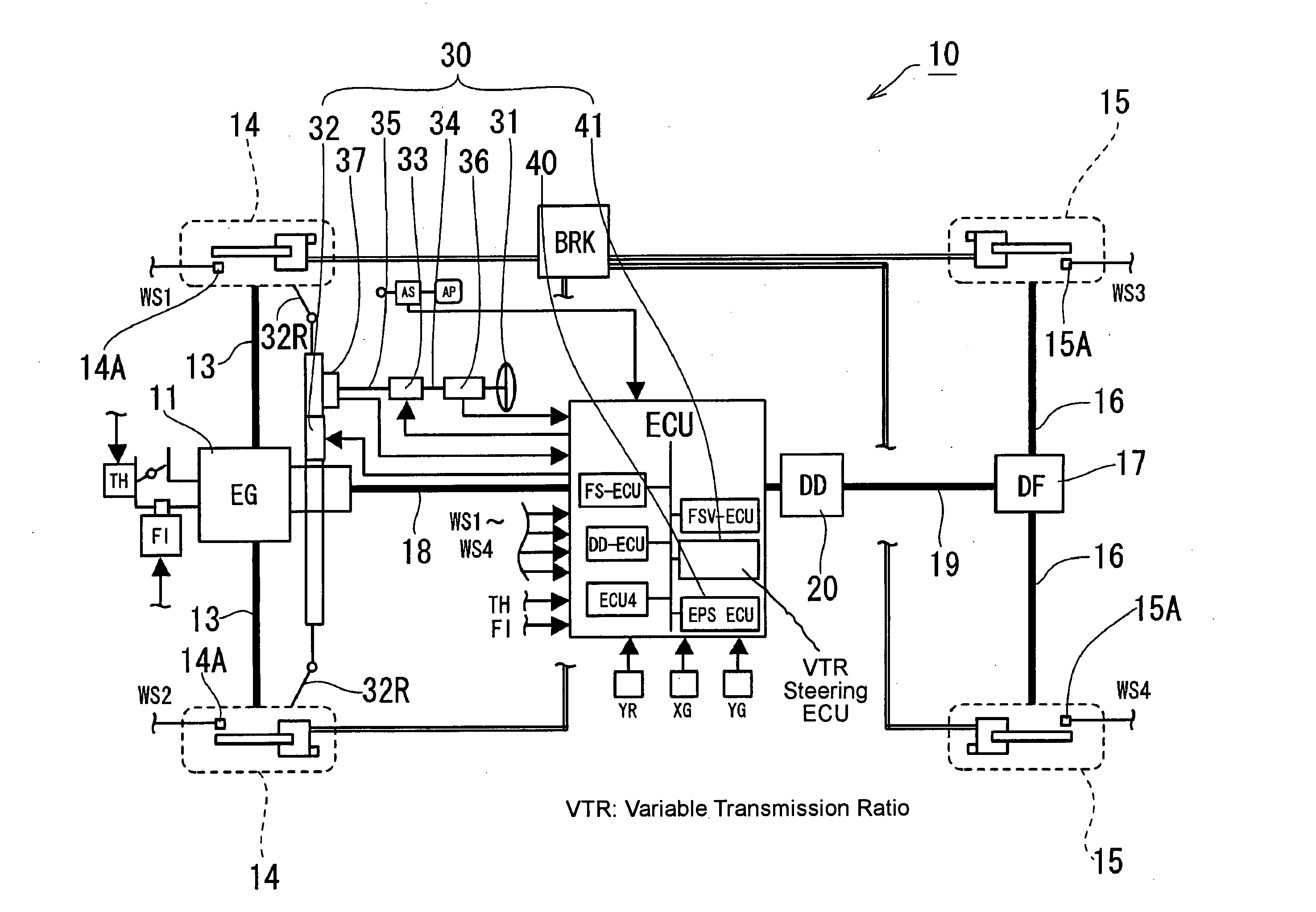
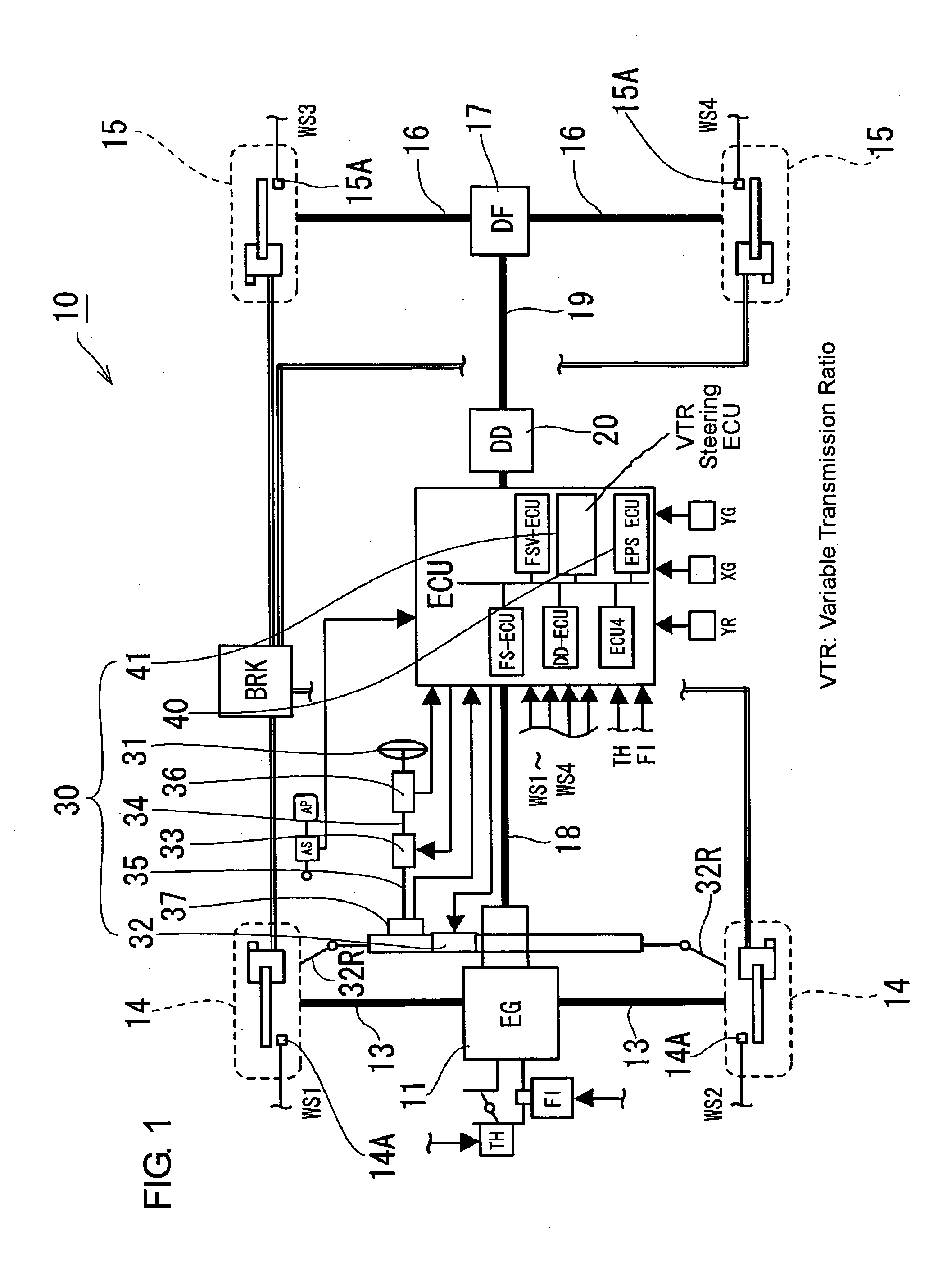
[0027] A first embodiment of the present invention will be described with reference to FIGS. 1 to 13. FIG. 1 shows main components included in a steering mechanical train 32-37 and a traveling drive train 11, 17-20 of a vehicle 10 incorporating a steering system 30 according to the present invention. First of all, the construction of the traveling drive train 11, 17-20 will be described. The vehicle 10 has an engine 11 mounted on the front side (left side as shown in FIG. 1). A transaxle (not shown) integrated with the engine 11 is provided with a transmission, a transfer and a front differential, and the drive power of the engine 11 is transmitted to front drive shafts 13, 13 through the transmission and the front differential, so that front wheels 14, 14 are driven which correspond to steerable wheels in the present invention.

[0028] The transfer of the transaxle has coupled thereto a front end portion of a front propeller shaft 18. A rear end portion of the front propeller shaft ...


PUM


Abstract

In a steering system 30, a transmission ratio R1 which is determined in dependence on the vehicle speed by reference to a transmission ratio decision map is multiplied with a first transmission ratio alteration gain g10 which is determined in dependence on the distribution of a traveling drive torque from an engine 11 to front wheels 14 and rear wheels 15, thereby to alter the ratio R1 of steering torque distribution from a steering handle 31 to the front wheels 14, whereby the variation of the steering feeling due to an increase or decrease in the distribution of the traveling drive torque to the front wheels 14 can be suppressed. Further, the transmission ratio R1 is multiplied with a second transmission ratio alteration gain g11 which is determined in dependence on the gradient of the road surface by reference to a second transmission ratio alteration map, thereby to alter the transmission ratio R1, whereby the variation of the steering feeling due to the variation of the gradient can also be suppressed.

Description

[0001] This application is based on and claims priority under 35 U.S.C. 119 with respect to Japanese Application No. 2004-112782 filed on Apr. 7, 2004. BACKGROUND OF THE INVENTION [0002] 1. Field of the Invention [0003] The present invention relates to a steering system capable of altering the mode in which steerable wheels follow to the manipulation of a steering handle, in dependence on the traveling state of a vehicle. [0004] 2. Discussion of the Related Art [0005] Heretofore, as steering systems of this kind, there have been known for example, an electric power steering device, (refer to Patent Document 1) capable of altering the assist force for the steering handle manipulation in dependence on the vehicle speed and a variable transmission ratio steering device capable of altering the transmission ratio between a steering handle and steerable wheels in dependence on the vehicle speed (refer to Patent Document 2). Further, there has recently been developed a vehicle capable of s...

Claims


Application Information

Patent Timeline
IPC IPC(8): B62D5/00B62D5/04B62D5/22B62D6/00B62D6/04B62D101/00B62D103/00B62D111/00B62D113/00B62D117/00B62D137/00
CPCB60W10/10B60W10/20B62D5/008B62D6/007B62D6/008B62D6/04
Inventor KATO, HIROAKITAKEUCHI, SHINJIMOMIYAMA, MINEKAZUOHNO, AKIHIROMURAKAMI, TSUYOSHI
Owner JTEKT CORP
Learn More