Chromatographic column and methods for controlling sorbent density

a sorbent density and chromatographic column technology, applied in the field of chromatographic columns, can solve the problems of voids or dead volumes, voids having a detrimental effect on the performance of the column, and within the column's packing bed, so as to promote predictable and simplified transfer of chromatographic methods, improve the stability of the column bed

Active Publication Date: 2005-10-13
WATERS INVESTMENTS
View PDF31 Cites 30 Cited by
  • Summary
  • Abstract
  • Description
  • Claims
  • Application Information

AI Technical Summary

Benefits of technology

[0010] The partially assembled column tubes of the present invention have a first column sorbent bed volume (X). This first column sorbent bed volume (X) can be any volume within an appropriate range defined by a particular column. When the column is assembled, defined herein as having both filter assemblies affixed to the two ends of the column tube, the column possess a second column sorbent bed volume (Z) that is always less than the first column sorbent bed volume (X) giving the formula “Z<X”. This is due to the compression of the sorbent bed reducing the bed volume by the volume occupied by the protruding filter assembly(s), i.e., volume (Y).
[0013] In the present invention, the porous inlet filter can be affixed to the filter housing as one continuous piece, alternatively, the inlet filter can be securely fastened to the filter housing permitting different size inlet filters to be employed using the same basic housing unit. A portion of the porous inlet filter is disposed within the interior chamber of the column tube when affixed to an end of the column tube displacing or compressing bed volume “X” by volume “Y”. The extent to which the inlet filter is disposed into the interior of the column tube is predetermined and fixed. Different size inlet filters can be used depending upon the desired depth of penetration into the interior chamber of the column tube. The function of the protruding inlet filter is to mitigate or obviate voids or dead volume occurring within the interior chamber of the column tube caused by, for example, pre-compression of the sorbent bed.
[0015] The column designs and methods for achieving high sorbent bed density as described herein provide the advantage of improving column bed stability as compared to conventional columns which are notorious for instability. A further advantage is the simplicity and inexpensive cost required for fabricating the column of the instant invention. Unlike columns of the prior art in which moving piston or radial compression devices are described, the columns of the present invention have a static system that does not vary over time which establishes a fixed final column volume thus promoting predictable and simplified transfers of chromatographic methods.

Problems solved by technology

Over time, these forces may disrupt the packing bed of the column resulting in voids or dead volume (V0) within the column's packing bed.
These voids have a detrimental effect on the performance of a column.
Voids can in effect serve as mixing chambers within the confines of the column leading to the loss of column efficiency.
For example, the practitioner may observe excessive peak tailing over time using a standard analyte, such peak tailing is indicative of a poor column.
An issue that plagues practitioners of chromatography is how to mitigate this loss of column performance.
However, these designs are typically very complex requiring multiple components and seals and are therefore inherently more expensive to produce.
Additionally, the columns with these movable devices require that the column tube itself be significantly larger and therefore much less convenient to use.
Further, these columns with movable devices do not contain a fixed volume of sorbent, which can lead to difficulty in predicting analyte retention times and the scaling of chromatographic methods across different column sizes

Method used


Image

  • Chromatographic column and methods for controlling sorbent density
  • Chromatographic column and methods for controlling sorbent density
  • Chromatographic column and methods for controlling sorbent density

Examples


example

[0056] The following example is intended to illustrate an embodiment of the present invention and should not be viewed as limiting the scope of the instant invention in any manner.

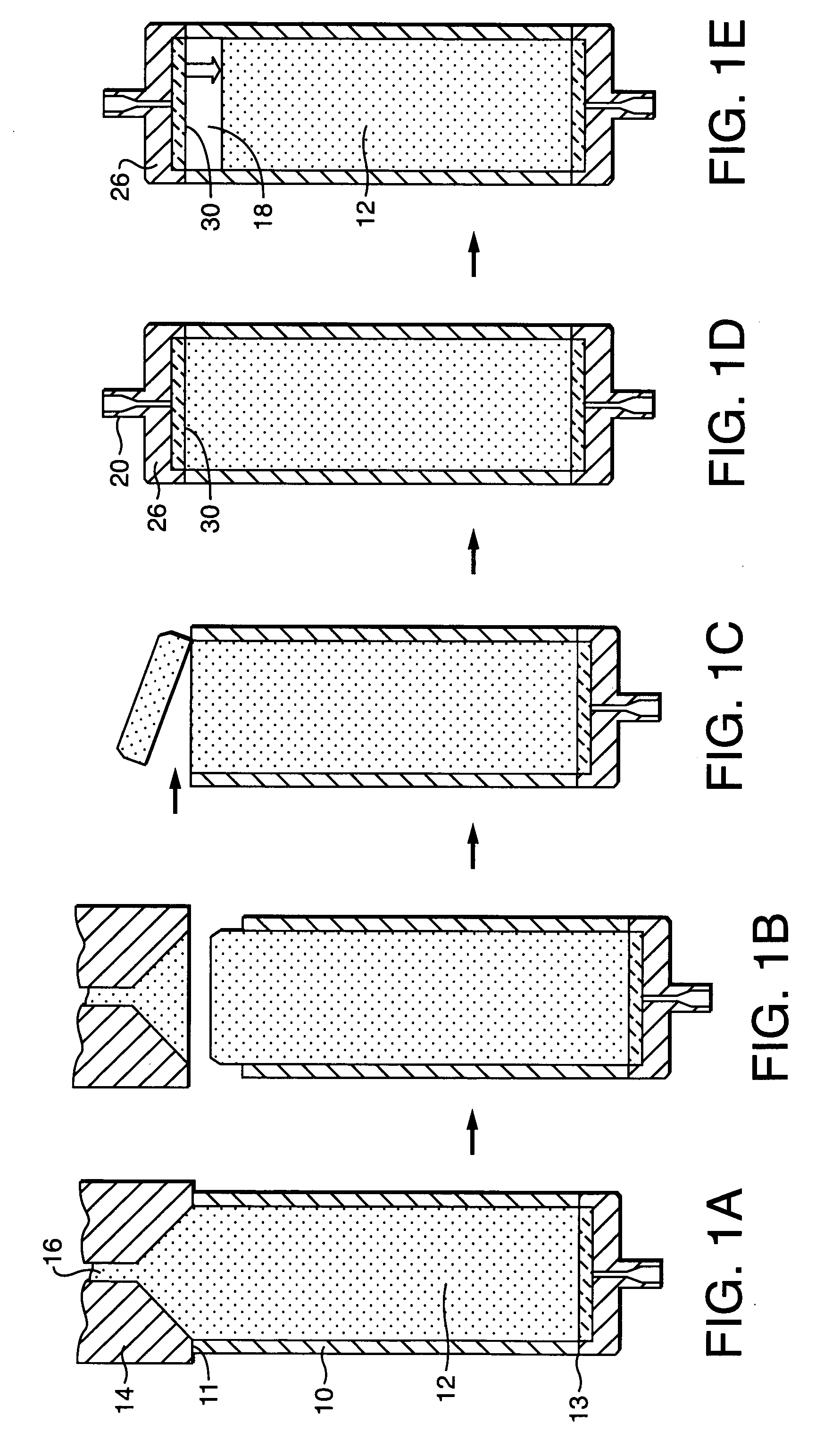
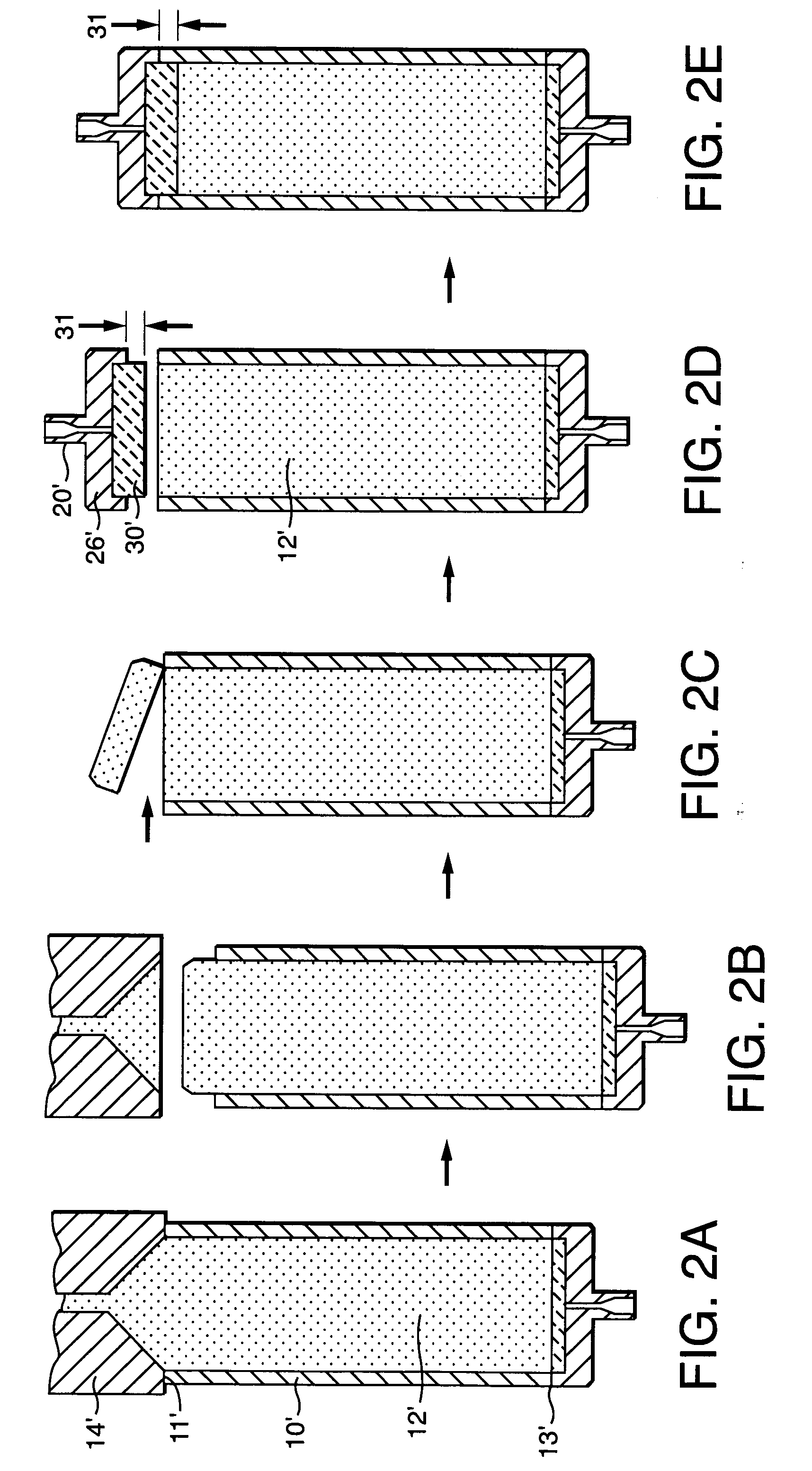
[0057] A series of columns are packed having 50 mm internal diameter and 100 mm initial length. Each column has an inlet filter / end fitting as described in FIG. 3 where the inlet filter extends inside the length of the column at distances of 1.5 mm, 3 mm, 5 mm, and 7 mm. Columns are packed with Waters' 5 μm, Xterra Prep MS C18 sorbent by preparing a slurry containing 140 g sorbent in 1550 mL of a toluene / cyclohexanol mixture (50 / 50 by volume), and pumping the slurry into the column at a pressure of 6000 psi. Once packed, excess sorbent is scraped flush with column face, and the inlet filter / end fitting is inserted into the column end and sealed in place with the threaded column end fitting.

[0058] Each column is tested for peak shape and efficiency by HPLC using a mobile phase consisting of a 50 / 50 aceton...


PUM

PropertyMeasurementUnit
sizeaaaaaaaaaa
diameteraaaaaaaaaa
pressureaaaaaaaaaa

Abstract

Disclosed herein are apparatus and methods for mitigating column bed compression over time. This invention provides for an improved column design and method of controlling bed density in a chromatographic column using a protruding portion of a filter assembly. The invention results in a higher sorbent bed density than can normally be achieved using a fixed length column of conventional design. The invention may be implemented as a unique filter assembly or as a column tailored for the application and a matching filter assembly.

Description

CROSS REFERENCE TO RELATED APPLICATIONS [0001] This application claims benefit of and is a continuation of International Application No. PCT / US03 / 28098, filed Sep. 8, 2003 and designating the United States, which claims benefit of and priority to U.S. Provisional Application No. 60 / 409,600, filed Sep. 10, 2002. The entire contents of these applications are incorporated herein by reference.FIELD OF INVENTION [0002] The present invention relates to chromatography columns, in particular, to apparatus and methods for achieving high sorbent density within said columns. BACKGROUND OF THE INVENTION [0003] A common method used to separate analytes within a sample is liquid chromatography. Liquid chromatography employs specific chromatographic columns and one or more mobile phases used to both equilibrate the column and elute analytes therefrom. Chromatography columns are used to effectuate the separation, purification and study of analytes contained within a homogeneous or heterogeneous sam...

Claims


Application Information

Patent Timeline
Patent Type & Authority Applications(United States)
IPC IPC(8): B01D15/08B01D15/20B01D15/22B01D15/32B01D15/34B01D15/36B01D15/38B01J20/281B01J20/283G01N30/16G01N30/52G01N30/56G01N30/60G01N30/62G01N30/72G01N30/74G01N30/88
CPCB01D15/206B01D15/22B01D15/325B01D15/34B01D15/362B01D15/363B01D15/3804B01J20/283B01J20/285G01N30/6004G01N30/6026G01N30/603G01N2030/522Y10T29/49604
Inventor IZZO, GARY S.FISK, RAYMOND P.BELANGER, JONATHANZINITI, DONALD E.TUVIM, YURI
Owner WATERS INVESTMENTS
Why Eureka
Try Eureka