Cask and method of producing the same

a production method and technology of a cask are applied in the field of cask and a production method, which can solve the problems of not clear if it can be realized, increase the cost of the manufacturing of the cask b>500/b>, etc., and achieve the effects of reducing the labor for forming the groove, reducing production time, and reducing production costs

Inactive Publication Date: 2005-10-13
MITSUBISHI HEAVY IND LTD
View PDF6 Cites 45 Cited by
  • Summary
  • Abstract
  • Description
  • Claims
  • Application Information

AI Technical Summary

Benefits of technology

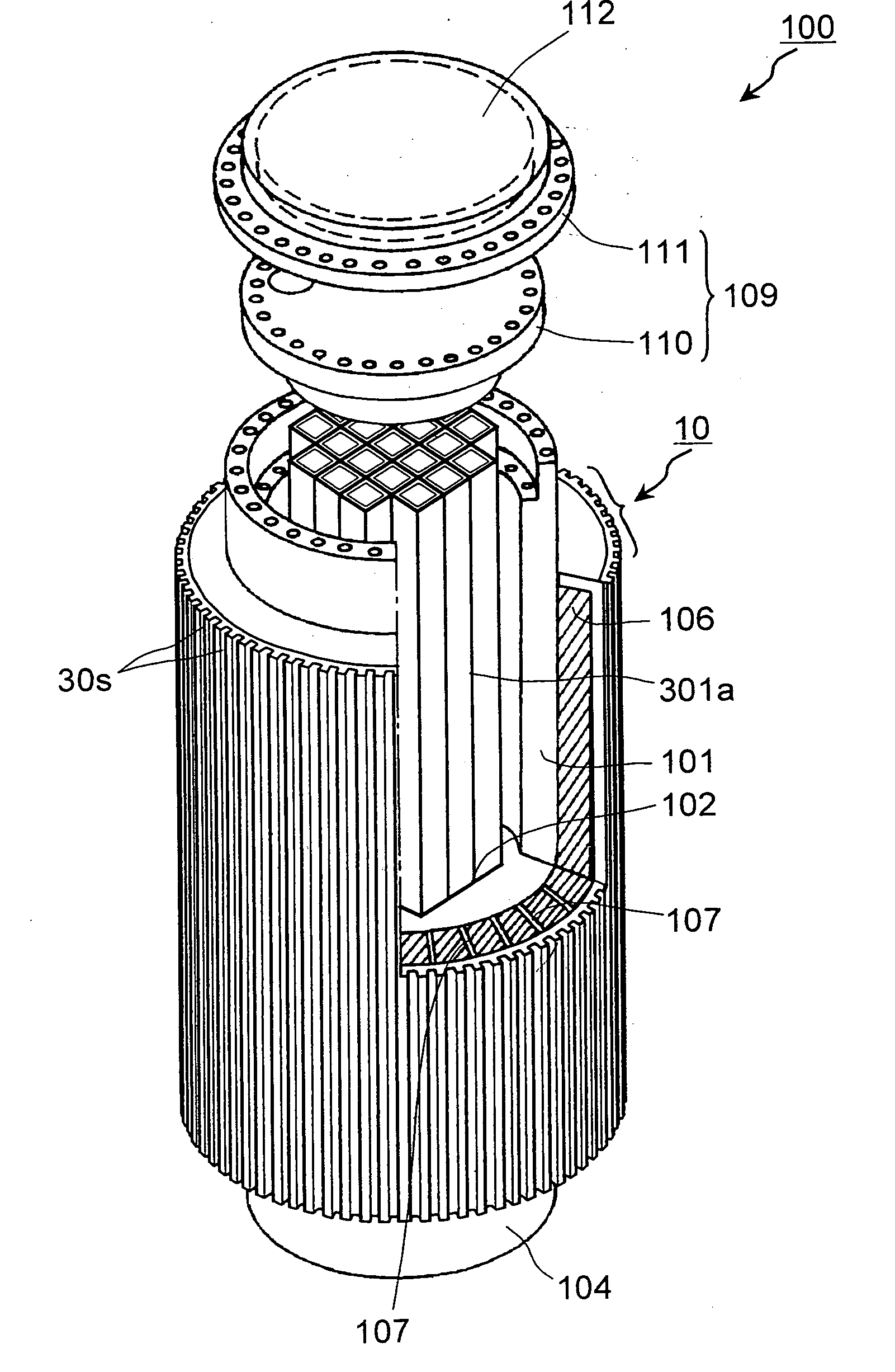
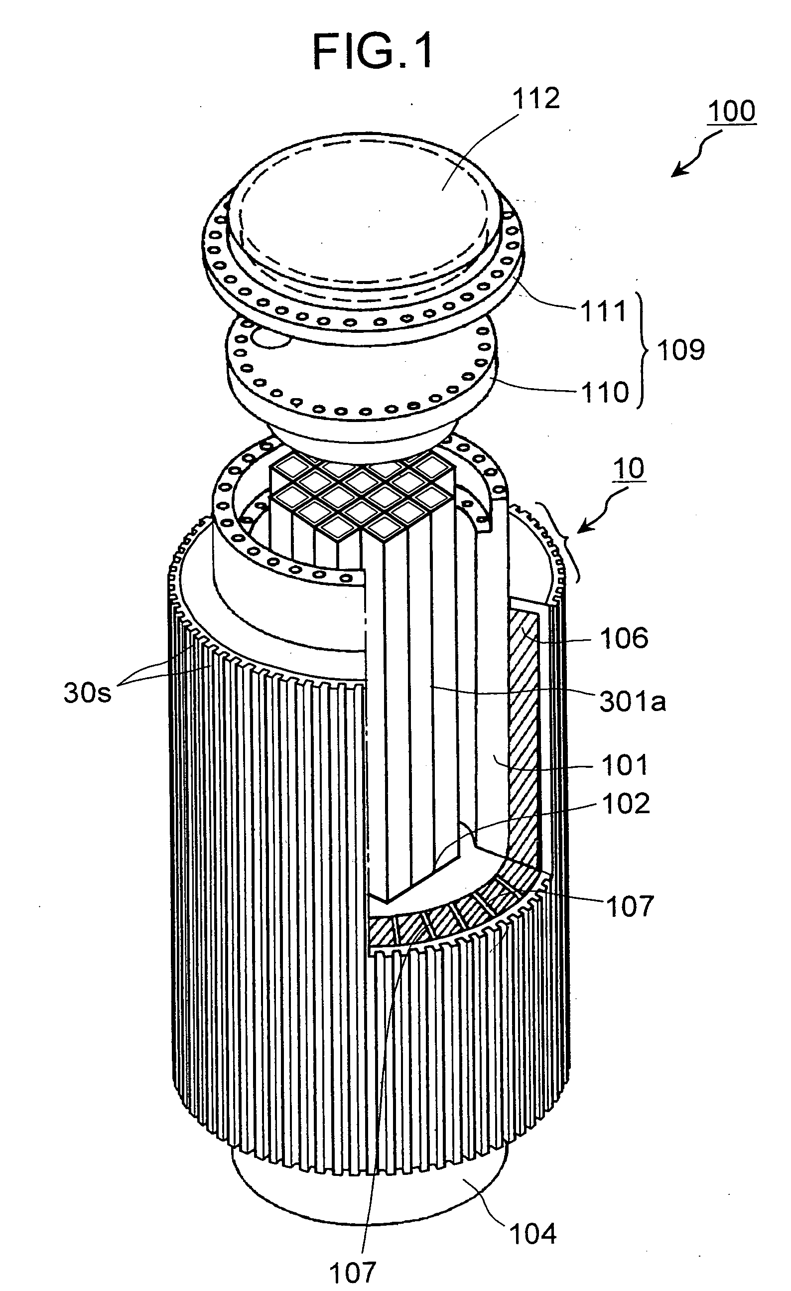
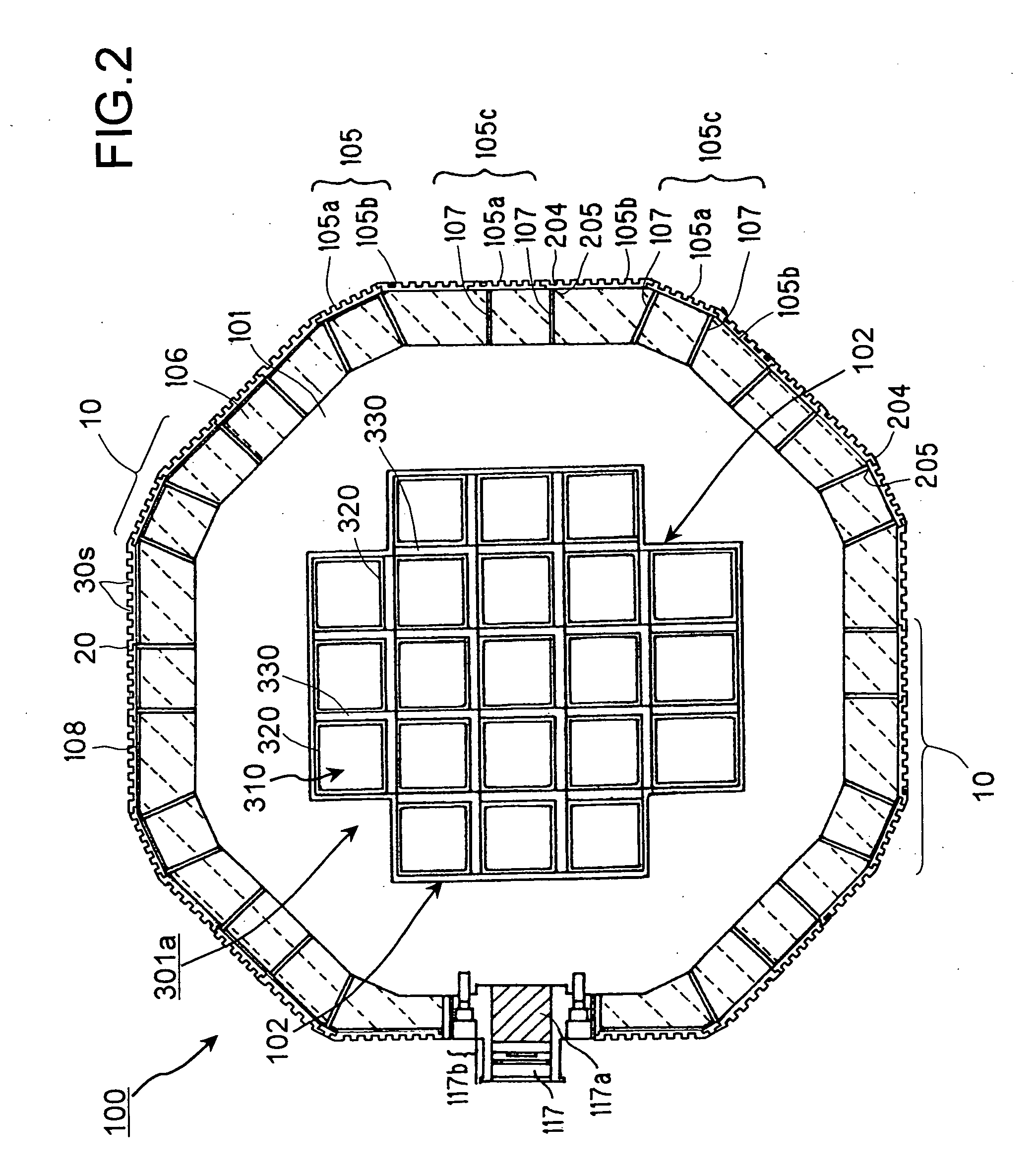
[0011] In the cask, since a plurality of grooves directed to at least one of the axial and circumferential directions of the trunk body are formed on the outside of the outer casing, the surface area of the outer casing can be increased than in a cask without grooves. As a result, much heat can be released to the air than that of the cask without grooves. Therefore, even when a spent fuel assembly having high burnup is stored, sufficient safety can be ensured. Since the outer casing is formed by combining a plurality of band-like members having grooves formed thereon, the outer casing can be produced easily without performing casting or bending. Further, even when the cross section of the trunk body is circular or polygonal, since the outer casing is formed by combining the band-like members, the cask can be easily produced.
[0077] Therefore, since a plurality of grooves can be formed at the same time, the labor for forming the grooves can be reduced considerably. Particularly, when a cask having an outer casing formed by combining a plurality of band-like members with the grooves formed on the surface thereof is produced, band-like members with grooves formed thereon can be efficiently produced, thereby enabling considerable reduction in production time.

Problems solved by technology

Further, insufficient heat dissipation from the outer casing 503 necessitates a material having an excellent heat resistance for the material forming the basket 509, thereby causing a cost increase in the manufacturing of the cask 500.
However, a specific method of fitting the outer casing in the trunk body of the cask via the heat transfer fins is not disclosed, and hence it is not clear if it can be realized.

Method used


Image

  • Cask and method of producing the same
  • Cask and method of producing the same
  • Cask and method of producing the same

Examples


third modification example

(Third Modification Example)

[0212]FIGS. 30A to 30C are schematics of the outer casing of the cask according to a third modification example of the first embodiment. An outer casing 13 of this cask has a substantially similar configuration to that of the outer casing 10 of the cask according to the first embodiment, but is different in that the cross-sectional shape of at least one of a groove 33s and a radiating fin 33f, being a protrusion divided by the grooves 33s, is formed in a circular-arc shape. The configuration of other parts is the same as in the first embodiment, and the explanation thereof is omitted, and like reference signs designate like parts.

[0213] As shown in FIGS. 30A to 30C, a plurality of grooves 33s having the circular-arc cross section are formed on the radiating surface 105p side of the band-like member 105a constituting the outer casing 13. The radiating fins 33f are formed by the grooves 33s on the radiating surface 21p side of the band-like member 105a and...

sixth embodiment

[0236]FIGS. 40A and 40B are assembly diagrams of a cask according to a sixth embodiment of the present invention. FIGS. 41A to 41C are cross sections cut along line A-A in FIG. 40A. In this cask 400, the grooves 30s directed to the axial direction (Z direction in the figure) of the trunk body 101 in the cask 400 are formed on the outside of a unit 402 formed in a ring shape, which constitutes an outer casing 401, and the unit 402 is sequentially inserted in the axial direction of the trunk body 101, and welded. As shown in FIGS. 42, 40A and 40B, the grooves 30s directed to the circumferential direction of the trunk body 101 in the cask 400 may be formed on the outside of the unit 402 formed in a ring shape, which constitutes the outer casing 401, and the unit 402 may be sequentially inserted in the axial direction of the trunk body 101, and welded. Though not shown, as explained in the modification example of the first embodiment, grooves directed to the axial direction and grooves ...

seventh embodiment

[0246]FIGS. 46A to 46E are partial cross-sections of a part of an outer casing of a cask according to a seventh embodiment of the present invention. This cask has a feature in that radiating fins 550f for transferring the decay heat from the trunk body 101 to an outer casing 19 and the outer casing 19 are integrally formed, and the grooves 30s directed to the axial direction of the trunk body 101 are formed on a radiating surface 550p.

[0247] The outer casing 19 is formed by combining units 550 obtained by bending a plate member in an L shape in cross section. The grooves 30s directed to the axial direction of the trunk body 101 are formed on the radiating surface 550p side of the unit 550, and protrusions divided by the grooves 30s become the radiating fins 30f. The grooves 30s may be provided toward the circumferential direction of the trunk body 101, or may be provided toward both the axial direction and the circumferential direction of the trunk body 101.

[0248] One end 550t1 of...


PUM


Abstract

A plurality of grooves is formed on a radiating surface side of band-like members constituting an outer casing of a cask. By the grooves, radiating fins are formed on the radiating surface side of the band-like member and the like. Heat transfer fins are respectively welded to the opposite sides of the band-like member, leaving the opposite edges thereof. The heat transfer fins are welded to buildup portions on the surface of a trunk body. The band-like member and the heat transfer fins form a unit with a U-shaped cross-section, and the units are welded on the surface of the trunk body at a predetermined interval. A step portion is respectively formed at the opposite edges of the band-like member, and a step portion of the band-like member is fitted to the step portion, and welded.

Description

TECHNICAL FIELD [0001] The present invention relates to a cask for containing and storing spent fuel assembly with excellent heat dissipation performance to dissipate decay heat of the spent fuel assembly to the air, and a method of manufacturing the cask. BACKGROUND ART [0002] A nuclear fuel assembly at the end of the nuclear fuel cycle, which has been irradiated to the extent that it is no longer usable, is referred to as a spent fuel assembly. Since the spent fuel assembly includes highly radioactive materials such as FP, it is necessary to thermally cool down the spent fuel assembly. Therefore, the spent fuel assembly is cooled down in a cooling pit in a nuclear power plant for a predetermined period (one year to three years). Thereafter, the spent fuel assembly is contained in a cask that is a radiation shielding container, transported to a reprocessing facility, and stored. The spent fuel assembly is inserted in a basket cell installed in the cask one by one to ensure an appro...

Claims


Application Information

Patent Timeline
Patent Type & Authority Applications(United States)
IPC IPC(8): G21F5/012G21F5/10G21F5/12G21F5/00G21F5/008
CPCG21F5/00G21F5/008G21F5/12G21F5/10G21F5/012Y02E30/30G21C19/32G21F9/36
Inventor TAMAKI, HIROKI
Owner MITSUBISHI HEAVY IND LTD
Why Eureka
Try Eureka