Capillary weld extension with thermal isolation

a thermal isolation and capillary weld technology, applied in the direction of branching pipes, fluid pressure measurement, instruments, etc., can solve the problems of ultra-pure materials outgasing, corrosive construction of remote seal systems, and high temperature outgasing of gas into fill fluid, so as to prevent capillary contamination

Active Publication Date: 2005-10-13
ROSEMOUNT INC
View PDF11 Cites 39 Cited by
  • Summary
  • Abstract
  • Description
  • Claims
  • Application Information

AI Technical Summary

Benefits of technology

[0010] There is a need in the remote seal art for a capillary seal system that is not susceptible to outgassing problems. Additionally, there is a need in the art for a remote seal system that can be installed in the field without requiring new or additional equipment to prevent capillary contamination.

Problems solved by technology

However, the housing of the remote seal may partially contact the process medium in some embodiments.
Unfortunately, the metallic, corrosion resistive construction of remote seal systems is known to outgas at high temperature.
Diffusion of gases into the fill fluid is detrimental to the seal performance, particularly in vacuum applications.
However, even ultra-pure materials outgas when exposed to high temperatures over a period of time.
Unfortunately, transferring this technique to remote seals in general is challenging due to the complex offering of remote seals available.
Moreover, while remote seal metal parts can be baked out as components to address gas source problems, this technique does not address the outgassing due to the weld joints.
An assembly bake of remote seal systems is extremely undesirable because of the multiple configurations offered for capillary size, length, and armor material.
The assembly bake would also have to be part of the manufacturing process, adding significant process time and requiring multiple ovens worldwide for capacity reasons.
Moreover, bakeout of an assembly with a polyvinyl chloride (PVC) armored capillary tube would be largely ineffective for high temperature devices, because the PVC could not withstand the high temperature bakeout required to eliminate outgassing from the corrosion resistive remote seal body.

Method used


Image

  • Capillary weld extension with thermal isolation
  • Capillary weld extension with thermal isolation
  • Capillary weld extension with thermal isolation

Examples


Embodiment Construction

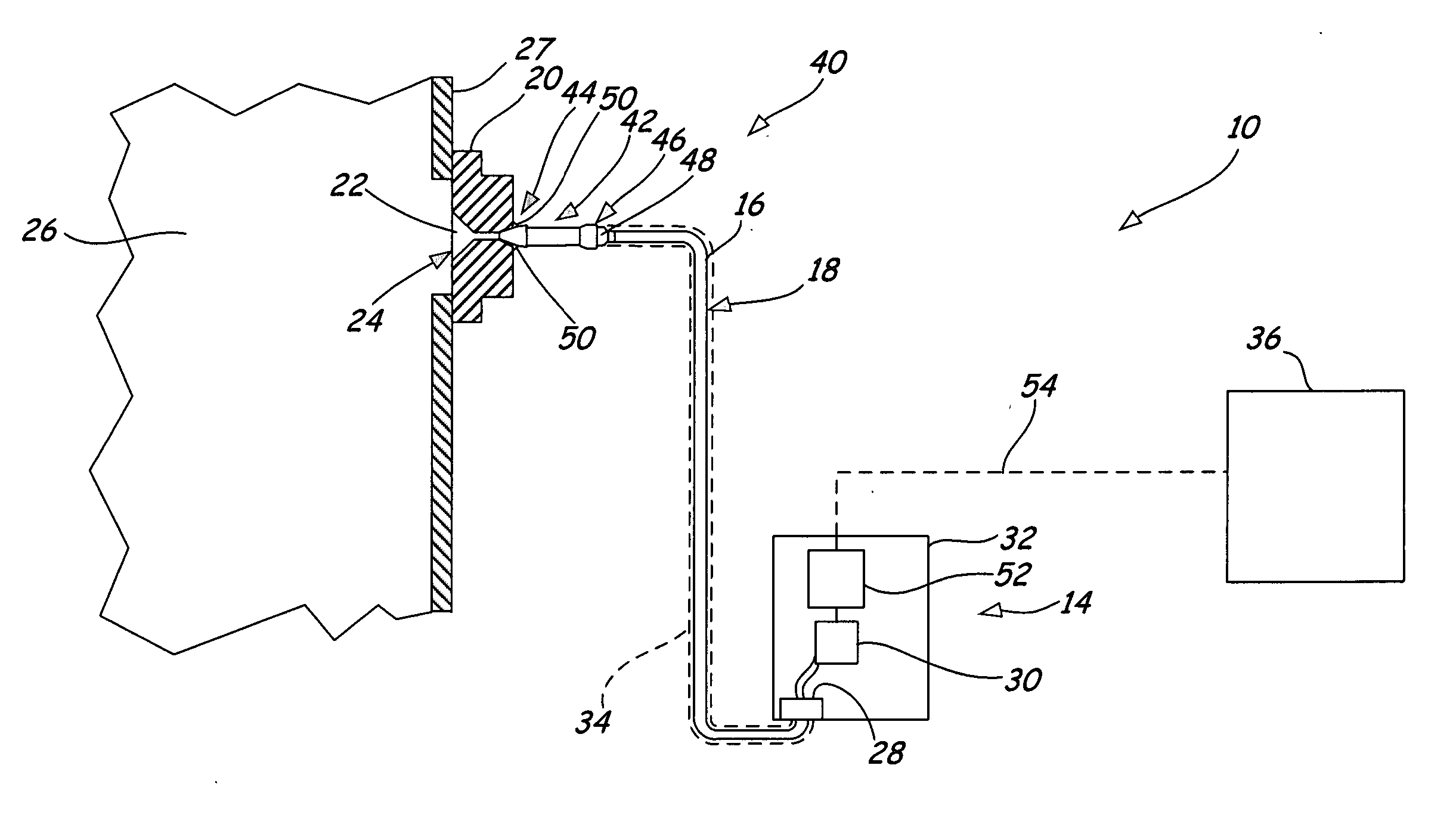
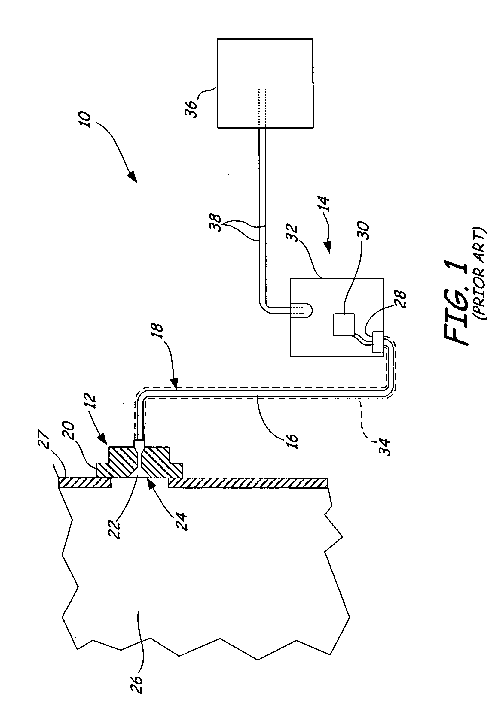
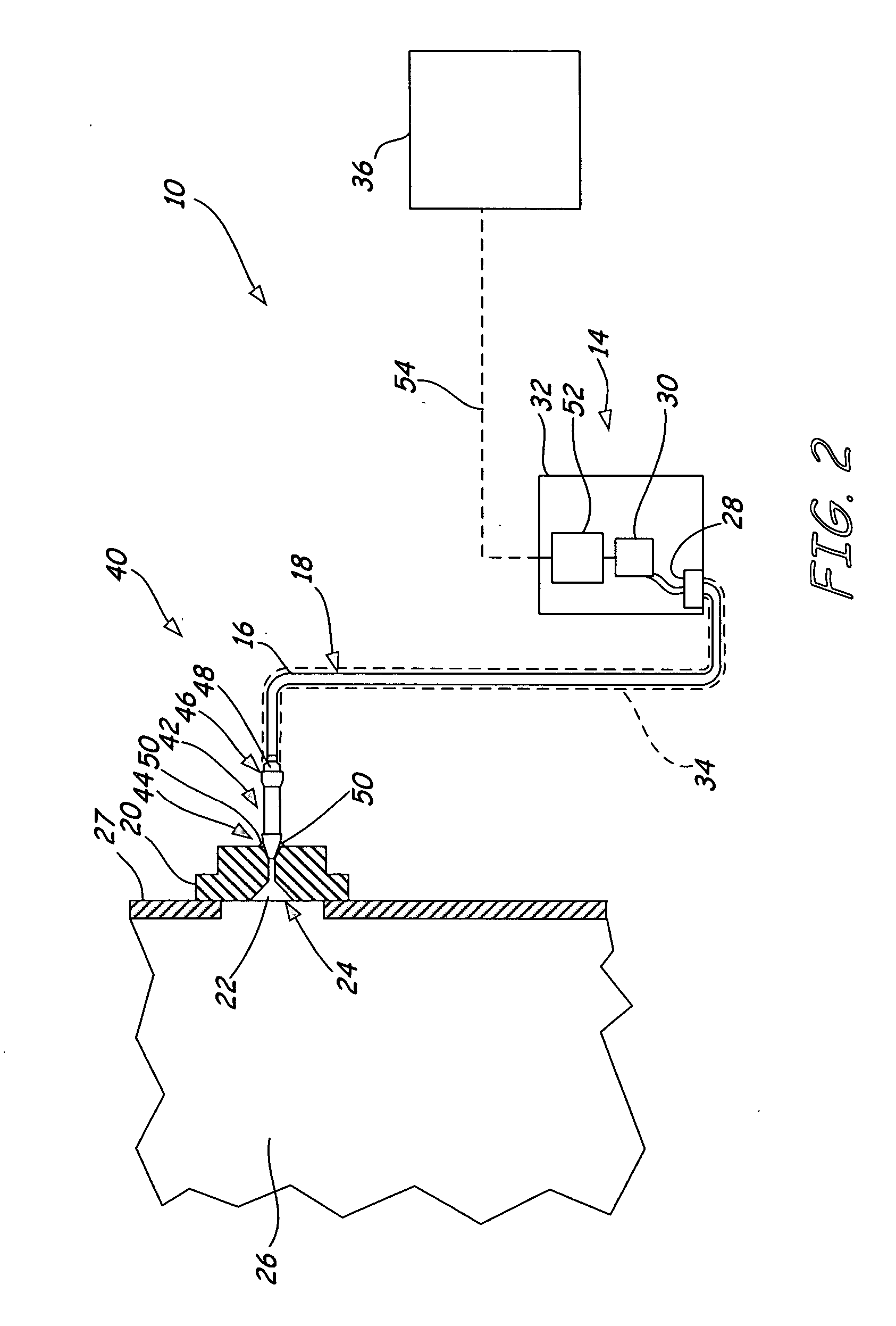
[0018]FIG. 1 shows a flush mount remote seal assembly 10 (which may be a “flanged-flush” style or a “pancake style”). Generally, the remote seal assembly 10 includes a remote seal 12 coupled to a transmitter 14 by a capillary tube 16, which is filled with a fill fluid 18. The capillary tube 16 is generally provided with capillary fittings on each end for connecting with a capillary opening (not shown) on the remote seal 12 and with a capillary connection (not shown) on the transmitter 14.

[0019] The remote seal 12 generally includes a housing (flange) 20, which defines a cavity 22. A diaphragm 24 extends across the cavity 22 in order to isolate the remote seal from the process fluid 26. The housing 20 may be provided with a fill fluid opening (not shown) for delivering the fill fluid 18 into the cavity 22 and the capillary tube 16 under a vacuum pressure. Additionally, openings (not shown) may be provided on the housing (flange) 20 for attaching the remote seal 12 to a conduit 27, a...


PUM

PropertyMeasurementUnit
outgassing temperatureaaaaaaaaaa
temperatureaaaaaaaaaa

Abstract

A remote seal assembly includes a seal body and an extension. The seal body defines a cavity with a diaphragm that seals the cavity from a process fluid. The extension is connected with the seal body on a first end and is configured for connection to a capillary tube on a second end. The extension defines a bore extending from the first end to the second end that is fluidically coupled to the cavity. A length of the extension is related to a temperature of the second end of the extension such that the second end of the extension is at or below an outgassing temperature of the material used to connect the extension and the capillary tube.

Description

BACKGROUND OF THE INVENTION [0001] The present invention relates to remote seal assemblies. More specifically, the present invention relates a remote seal assembly including capillary weld extension with thermal isolation for coupling a process control instrument to a process fluid. [0002] Some types of process control instruments, such as pressure transmitters, have a pressure sensor which is fluidically coupled to an isolation diaphragm by a capillary tube that is filled with a fill fluid. The isolation diaphragm comprises part of a subassembly called a “remote seal” or a “diaphragm seal”, which isolates the pressure sensor from corrosive process fluids being sensed. Pressure is transferred from the isolation diaphragm to the sensor through the fill fluid, which is substantially incompressible. The capillary or tube is typically flexible and may extend for several meters. The process medium exerts pressure on the isolation diaphragm which conveys the exerted pressure to the pressu...

Claims


Application Information

Patent Timeline
Patent Type & Authority Applications(United States)
IPC IPC(8): F16L41/08F16L13/02F16J15/14F15B3/00G01L19/06F16J15/52G01L19/04G01L19/00
CPCG01L19/0046G01L19/0681
Inventor SUNDET, PAUL CURTIS
Owner ROSEMOUNT INC
Why Eureka
Try Eureka