Optical wavelength add-drop multiplexer

a technology of optical wavelength and multiplexer, which is applied in the field of optical information transmission, can solve the problems of large problem, insufficient mechanism provided for optical wavelength add-drop multiplexers, and inability to detect wavelength errors, so as to prevent a count error of the number of wavelengths, prevent a wavelength error, and detect wavelength errors quickly

Inactive Publication Date: 2005-10-13
HITACHI LTD
View PDF10 Cites 43 Cited by
  • Summary
  • Abstract
  • Description
  • Claims
  • Application Information

AI Technical Summary

Benefits of technology

[0019] As for the problem, which is newly pointed out in the present invention, that a wavelength error of an optical add signal cannot be detected, this problem can be solved by providing the function of: measuring a wavelength of an optical add signal; judging whether or not a wavelength of an optical add signal is correct; only when an optical add signal having a correct wavelength is detected, judging that an optical add signal exists; or only when an optical add signal having a correct wavelength is detected, calculating the number of optical add signals. In particular, by displaying a measured value of a wavelength of the inputted optical add signal, information which can be used to judge whether or not a wavelength is correct, information about the number of wavelengths of an optical add signal having a correct wavelength, or an alarm based on the judgment as to whether or not a wavelength is correct, on a display unit such as a lamp, a LED, a liquid crystal, or a display screen, or by notifying a remote operator or other equipment of the above-mentioned information, it is possible to correctly notify an operator, a network administrator, or other transmission equipment, of a state of a wavelength error, and thereby to solve the wavelength error of the optical add signal more effectively.
[0023] In addition, as for the problem that a wavelength error of an optical add signal causes a failure, it is possible to solve this problem by placing, on the input side of the optical add signal, an optical filter that passes only an optical signal having a correct wavelength, or by placing, at a position before an optical detector for detecting the existence of an optical add signal, an optical filter that passes only an optical signal having a correct wavelength. To be more specific, it is possible to prevent a count error of the number of wavelengths from occurring in the device by providing a function by which only when optical add signals having correct wavelengths are inputted, it is judged that optical add signals exist.
[0025] According to the present invention, firstly, it becomes possible to detect a wavelength of an optical add signal, and to judge whether or not the wavelength is correct, both of which were not conventionally pointed out. Displaying, for an operator of the equipment, the result of the judgment as to whether or not the wavelength is correct, or transferring the result to other equipment through a network, makes it possible to easily detect a wavelength error of an optical add signal, which could not be conventionally detected. As a result, a period of time and the cost, which are required to solve the trouble, are reduced, making it possible to quickly recover a communication line.
[0026] Next, it is possible to prevent a count error of the number of wavelengths from occurring in the device by: detecting a wavelength error of an optical add signal; or providing a function whereby only when an optical add signal having a correct wavelength is inputted, it is judged that an optical add signal exists; or providing a function whereby only when an optical add signal having a correct wavelength is inputted, counting the number of wavelengths. As a result, it becomes possible to avoid the problems including: the degradation by a nonlinear optical effect caused by an insufficient signal-to-noise ratio of signal light, or caused by an excess of the optical power, resulting from improper settings of the optical output power of the optical amplifier, or the like; and a communication failure, caused by falling outside the allowable range of the optical power inputted into the optical receiver, or a breakdown of a receiver.
[0027] Moreover, according to the present invention, the broadcast and select type reconfigurable optical wavelength add-drop multiplexer can also be provided with a detection mechanism for detecting a wavelength error of an optical add signal, and an interlock mechanism for avoiding a failure caused by a wavelength error before it happens.

Problems solved by technology

The conventional optical wavelength add-drop multiplexer as described above, however, is not sufficiently provided with a mechanism for detecting a misconnection caused by a user, which is a large problem.
In particular, a problem which has not been conventionally pointed out is that a wavelength error of an optical add signal cannot be detected.
Accordingly, firstly, it is not possible to detect the occurrence of a misconnection in a work site.
Even if a communication line stops due to a trouble, it is difficult to solve the trouble, and therefore problems of time and cost arise.
Secondly, the conventional reconfigurable optical wavelength add-drop multiplexer 120 has a problem that because an optical add signal is judged to have been internally added, power settings of the optical signal, or the like, are improperly made, causing the signal degradation.
As a result, the optical output power is improperly set in the optical amplifiers 102-1 and 102-2.
Thus, if the optical signal power varies from a proper set value, there is a possibility that the following large problems will arise: a signal-to-noise ratio of a signal light is not sufficient; a nonlinear optical effect is caused by the excess optical power, resulting in the degradation; the optical power inputted into an optical receiver exceeds an allowable range, resulting in incapability of receiving, or a breakdown of a receiver; and the like.
However, the broadcast and select type reconfigurable optical wavelength add-drop multiplexer further has a third problem.
To be more specific, if an operator connects by mistake an optical transmitter, which handles the same wavelength as that of an optical through signal being transmitted or that of another optical add signal, to an optical add signal input fiber, an optical signal being used for information transmission cannot be transmitted, causing a serious failure.
Because these optical signals are modulated with information signals that differ from each other, there is a possibility that one, or both, cannot be received.
However, the broadcast and select type reconfigurable optical wavelength add-drop multiplexer does not have a mechanism for detecting a wavelength error of such an optical add signal, and an interlock mechanism for avoiding a failure caused by a wavelength error before it happens, which is the problem.
However, by use of this configuration, it is not possible to make a judgment as to whether or not a wavelength of the optical add signal is correct.

Method used


Image

  • Optical wavelength add-drop multiplexer
  • Optical wavelength add-drop multiplexer
  • Optical wavelength add-drop multiplexer

Examples


first embodiment

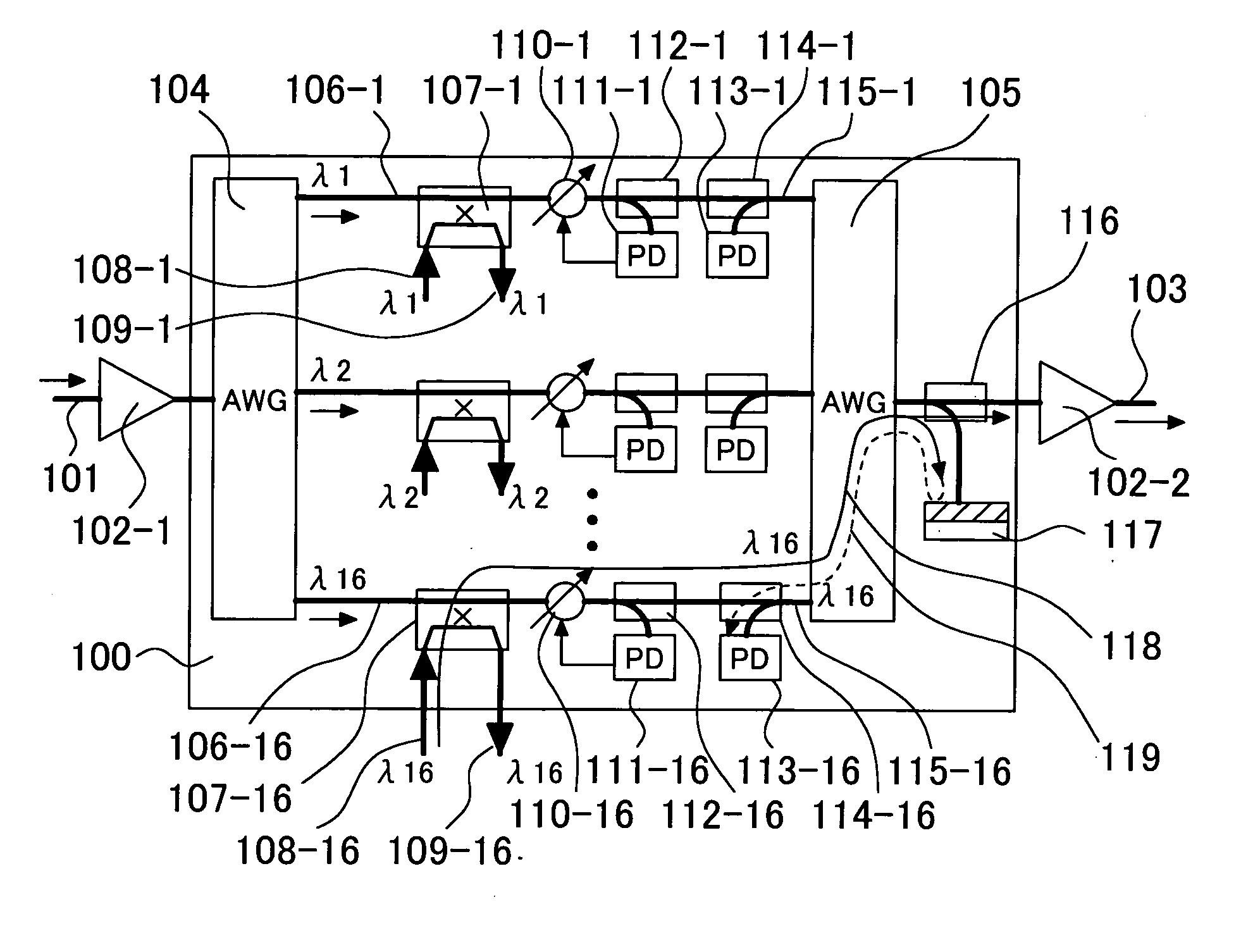
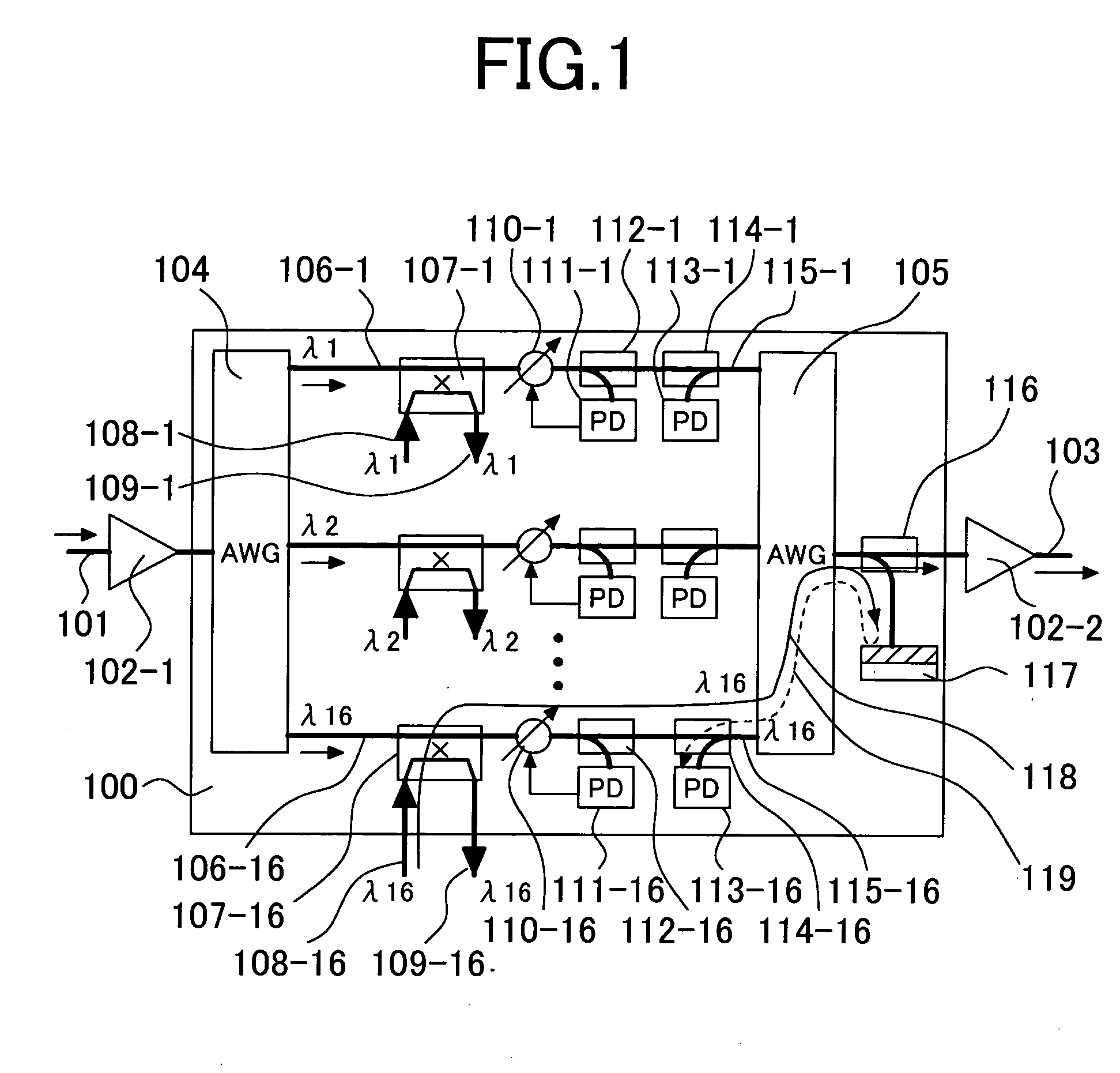
[0052]FIG. 1 is a configuration diagram illustrating a first embodiment of the present invention. FIG. 1 illustrates a configuration example of a reconfigurable optical wavelength add-drop multiplexer (ROADM) 100 to which the present invention is applied. This configuration is made by adding optical couplers 114-1 through 114-16, backward direction optical detectors 113-1 through 113-16, an optical coupler 116, and a mirror 117 to the conventional configuration shown in FIG. 2. The optical coupler 116 branches part of a wavelength division multiplexed optical signal output from the reconfigurable optical wavelength add-drop multiplexer 100, and then introduces the branched optical signal (for example, about from 1 to 20%) into the mirror 117. As a result, the part of the wavelength division multiplexed light is reflected and then passes through the optical coupler 116 again, and consequently enters a optical wavelength multiplexer 105 in the reverse direction. The wavelength divisio...

second embodiment

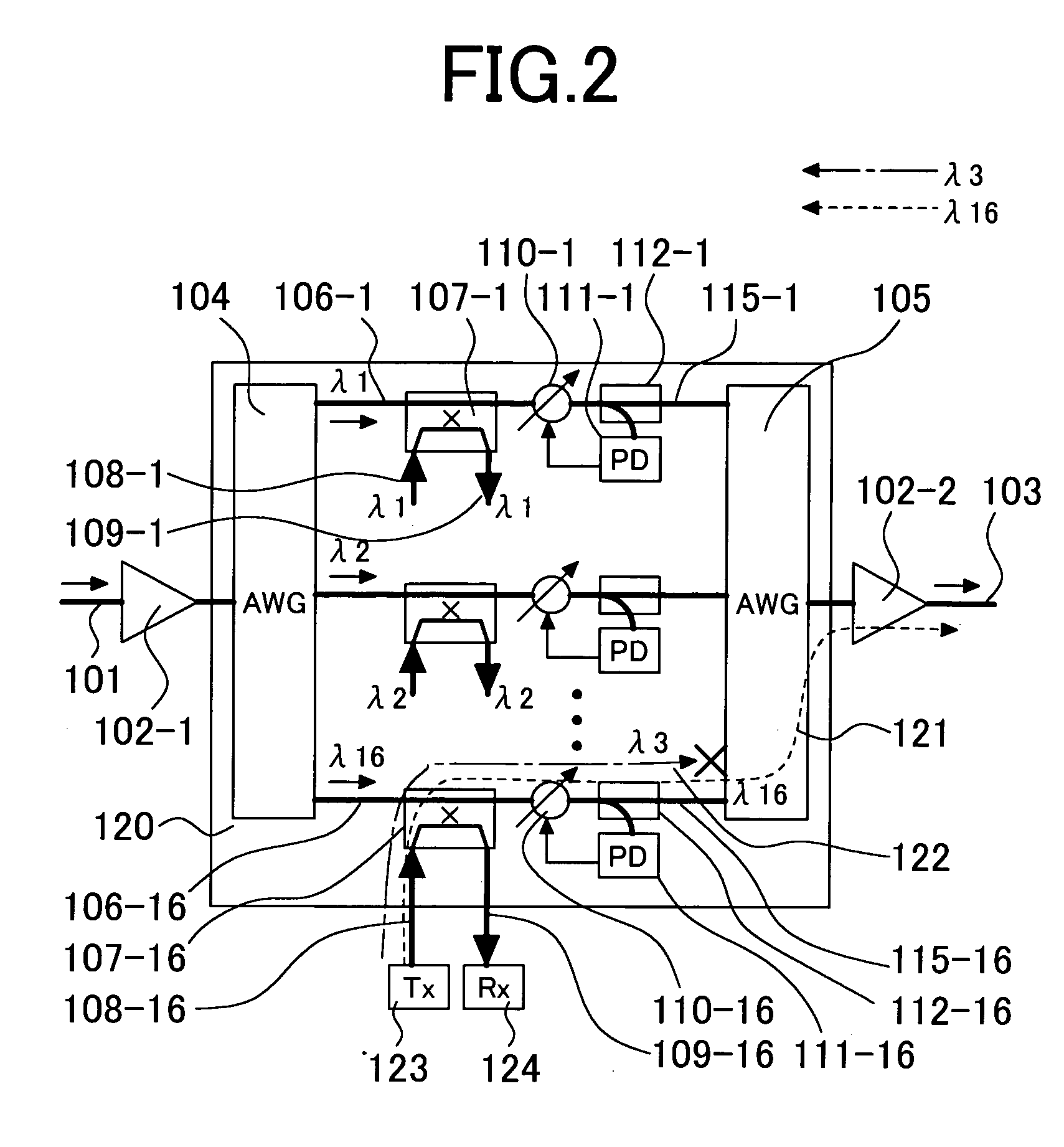
[0064]FIG. 8 is a configuration diagram illustrating a second embodiment of the present invention. This is an example in which part of a wavelength division multiplexed signal output to an output optical fiber 103 is branched by the optical coupler 116, and the branched wavelength division multiplexed signal is then inputted into the wavelength meter 160 where wavelengths of optical add signals are measured. For example, if the 2×2 optical switch 107-16 for switching an optical signal having the wavelength λ16 between the through state and the add state is in the add state, when an incorrect optical signal having the wavelength λ3 is inputted into the optical add signal input fiber 108-16, the optical signal is blocked by the optical wavelength multiplexer 105 as shown by the path 122. Accordingly, although the optical signal is detected by the forward direction optical detector 111-16, this optical signal does not arrive at the wavelength meter 160. On the other hand, when a correc...

third embodiment

[0066]FIG. 9 is a configuration diagram illustrating a third embodiment of the present invention. This is an example in which the plurality of input optical fibers 115-1 through 115-16 of the optical wavelength multiplexer are further provided, respectively, with optical couplers 163-1 through 163-16, optical bandpass filters 161-1 through 161-16 that passes only optical signals having the wavelengths 1 through 16 respectively to block the other wavelengths, and optical detectors 162-1 through 162-16 so that the judgment can be made as to whether or not an optical add signal having a correct wavelength has been detected. For example, as indicated by the path 118, part of an optical add signal having the wavelength λ16 inputted into the optical add signal input fiber 108-16 is branched by the optical coupler 163-16. After that, the branched part of the optical add signal passes through the optical bandpass filter 161-16 that passes only an optical signal having the wavelength λ16, an...


PUM


Abstract

It was difficult to detect a wavelength error. Further, a wavelength error of an optical add signal is accompanied by a calculation error of the number of wavelengths of a wavelength division multiplexing signal, which causes a set value of an optical signal level to become abnormal, resulting in the degradation of the optical signal. According to the present invention, part of an inputted optical add signal 118 is reflected by a mirror 117, and is thereby inputted into an optical wavelength multiplexer 105 in the reverse direction so that the optical add signal is returned to paths 115-1 through 115-16 corresponding to wavelengths λ1 through λ16. If the returned optical add signal is an optical add signal having a correct wavelength (in FIG. 1, λ16), the optical signal enters its corresponding backward direction optical detector 113-16. Accordingly, it is possible to check whether or not a wavelength of the optical add signal is correct.

Description

CLAIM OF PRIORITY [0001] The present application claims priority from Japanese application JP 2004-098258 filed on Mar. 30, 2004, the content of which is hereby incorporated by reference into this application. BACKGROUND OF THE INVENTION [0002] 1. Field of the Invention [0003] The present invention relates to optical information transmission that uses an optical fiber, and more particularly to an optical wavelength add-drop multiplexer. [0004] 2. Description of the Related Art [0005] The wavelength division multiplexed (WDM) optical transmission method is a very effective method for increasing the capacity of optical fiber communication. In this method, a plurality of optical signals, each of which has a wavelength different from the other, are multiplexed in one optical fiber to transmit information. The optical wavelength add-drop multiplexer is one of transmission equipments placed for respective nodes in optical fiber networks which carry WDM signals. The optical wavelength add-...

Claims


Application Information

Patent Timeline
Patent Type & Authority Applications(United States)
IPC IPC(8): H04J14/00G02B6/00H04B10/27H04B10/29H04B10/291H04J14/02
CPCH04J14/021H04J14/0227H04J14/0221H04J14/0212
Inventor KIKUCHI, NOBUHIKOSEKINE, KENROSASAKI, SHINYA
Owner HITACHI LTD
Why Eureka
Try Eureka