
System and method for filtering and detecting faint signals in noise

Inactive Publication Date: 2005-10-13
VIVOSONIC
View PDF14 Cites 12 Cited by
  • Summary
  • Abstract
  • Description
  • Claims
  • Application Information

AI Technical Summary

Benefits of technology

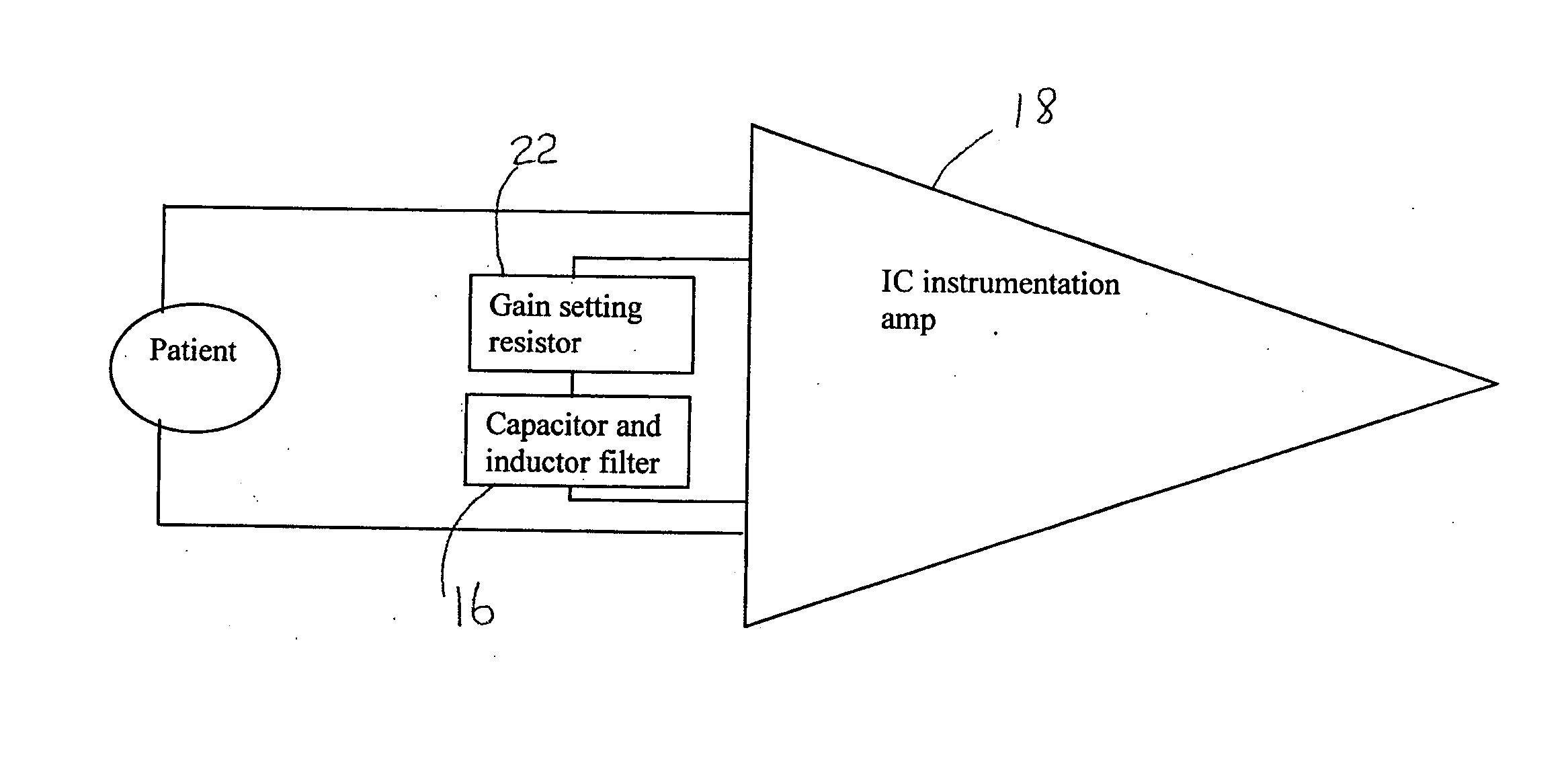
[0018] The present invention is intended to overcome at least some of the noted issues. In one embodiment of the invention, there is provided a system and method to filter a differential signal in which band-pass filtering is performed before amplification without adversely affecting common mode rejection ratio and input impedance. The use of band-pass filtering prior to amplification reduces the noise in the signal being amplified and allows higher gain to provide a clearer signal following amplification.
[0027] According to yet another embodiment of the invention, there is provided a method for filtering differential evoked potential signals. The method includes: receiving a differential evoked potential signal; and filtering the signal to reduce noise using a prefiltering network prior to amplification, the prefiltering network including a high-pass, low-pass, band reject or band-pass filter.
[0028] Again in this method, the filtering can be designed to reduce one or more of radio frequency interference, low-frequency noise and DC offset from the differential evoked potential signal.

Problems solved by technology

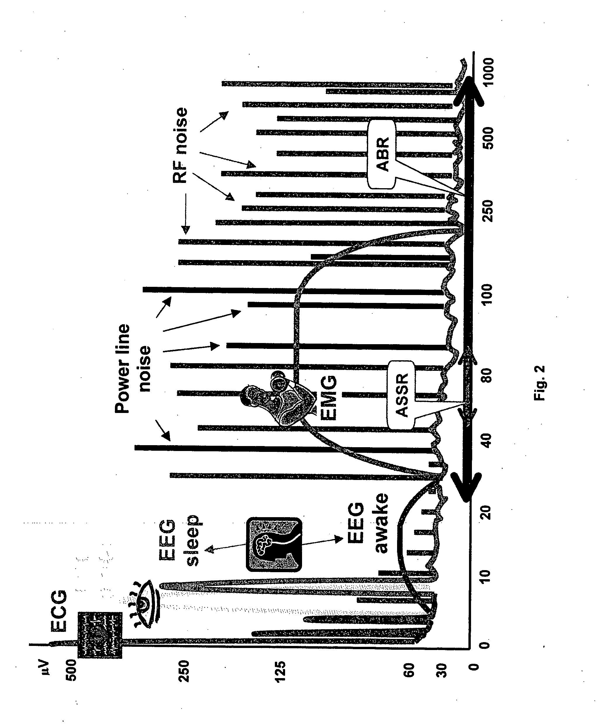
Interestingly, the physiological sources of noise, such as ECG, can be more problematic in infants than adults because an infant's heart is positioned more centrally, is generally larger relative to the body, is closer to the head, and beats faster.
In a conventional amplifier, using a large gain can result in saturation (reaching the limits of the amplifier's dynamic range), which, after filtering using a band-pass filter, distorts the signal and can leave “blank” periods or pauses in the signal (as illustrated in FIG. 4).
Conversely, using a lower gain reduces the signal-to-noise ratio (SNR) at the amplifier output, may require additional amplification and complicates signal detection in later processing.
A disadvantage of the first approach is that the common mode rejection ratio (CMRR) and input impedance of the amplifier are adversely affected because small differences in components connected to the input leads cause the common mode gain to increase.
A disadvantage of the second approach is that the gain of the first stage of the instrumentation amplifier generally has to be limited to avoid saturation.
Limiting the first stage gain adversely affects the SNR and the CMRR of the amplifier.

Method used


Image

  • System and method for filtering and detecting faint signals in noise
  • System and method for filtering and detecting faint signals in noise
  • System and method for filtering and detecting faint signals in noise

Examples


Embodiment Construction

[0038] In an embodiment of the present invention a method of filtering signals prior to amplification includes filtering (low-pass, high-pass, band-reject or band-pass filtering) the signal prior to the first stage of amplification, thus reducing unwanted noise and allowing higher gain. As a result, EP signals at the output have larger amplitude, contain much less noise, and have larger SNR.

[0039]FIG. 5 shows a system 10 for measuring EP signals according to an embodiment of the invention. The system 10 includes two active electrodes 12 and a ground electrode 14 that allow the determination of a differential EP signal. In this particular embodiment, the ground electrode 14 includes a prefiltering network 16 and an amplifier 18 (shown in FIG. 7). The active electrodes connect to the prefiltering network 16. The provision of the prefiltering network 16 and amplifier 18 in proximity to the ground electrode 14 allows for shorter leads 20, which reduces EMI because the shorter leads are...


PUM


Abstract

A system and method for filtering and detecting faint signals in noise by placing a filter prior to an amplifier. In particular, a system for filtering differential signals includes: a signal receiver for receiving a differential signal; a prefiltering network connected to the receiver for filtering the differential signal prior to amplification, the prefiltering network including a high-pass filter and / or a low-pass filter; and an amplifier connected to the filtering network. In contrast with the conventional approach of connecting the filter to the amplifier's inputs, the filtering network in a preferred embodiment of the invention is connected to the amplifier through the amplifier's gain resistor such that the input impedance and common mode rejection ratio of the amplifier is not adversely affected by the filtering. Band-pass filtering prior to amplification reduces the noise in the signal and allows higher gain to provide a clearer signal following amplification.

Description

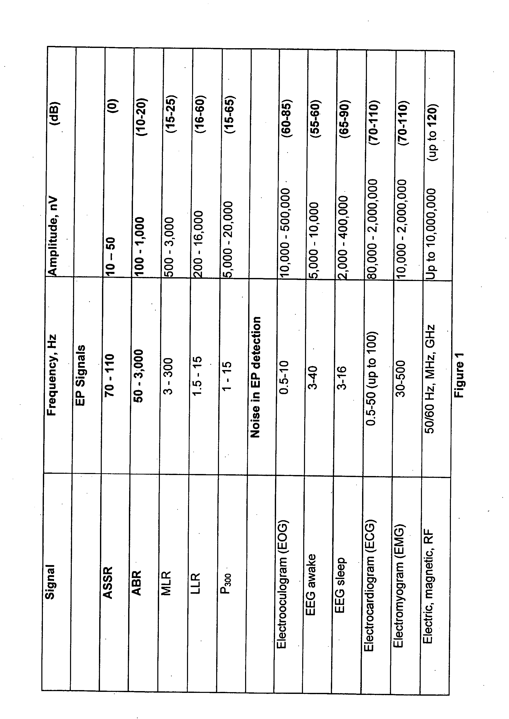
FIELD OF INVENTION [0001] This invention relates to the field of detecting faint electrical signals in noise and, more particularly, relates to a system and method for detecting evoked potential signals by filtering signals prior to amplification. BACKGROUND OF THE INVENTION [0002] Evoked potentials (EPs) are very faint electrical signals that are produced within the body when subject to stimulus. EPs can be used, for example, in auditory testing. In particular, Auditory Steady State Responses (ASSR) are signals that are in the range of 10-50 nV (1 nV is a billionth of a Volt). Another type of EP is the Auditory Brainstem Response (ABR), which is in the range of 100-1000 nV. [0003] When detecting EPs, the detection is affected by numerous types of electrical “noise” at the electrodes from external sources such as power lines, equipment in the area (including equipment used to stimulated the EP response), Radio Frequency interference and also from physiological sources, for example, ...

Claims


Application Information

Patent Timeline
IPC IPC(8): A61B5/04A61B5/0484
CPCA61B5/04004A61B5/04845A61B5/0484A61B5/30A61B5/38A61B5/377
Inventor KURTZ, ISAAC
Owner VIVOSONIC
Learn More