
Surveying apparatus and method of analyzing measuring data

a technology of measuring data and surveillance equipment, applied in the field of surveillance instruments and methods of analyzing measuring data, can solve the problems of inability to reliably and robustly detect the features of objects, the image detected by the camera is subject to disturbance, and the conventional methods of image processing may not always achieve satisfactory measurement, etc., to achieve the effect of high accuracy, easy identification and elimination

Inactive Publication Date: 2005-10-13
TRIMBLE JENA
View PDF5 Cites 23 Cited by
  • Summary
  • Abstract
  • Description
  • Claims
  • Application Information

AI Technical Summary

Benefits of technology

[0009] Embodiments of the present invention provide a surveying apparatus allowing improved detection of features of an object in an image recorded by a camera.
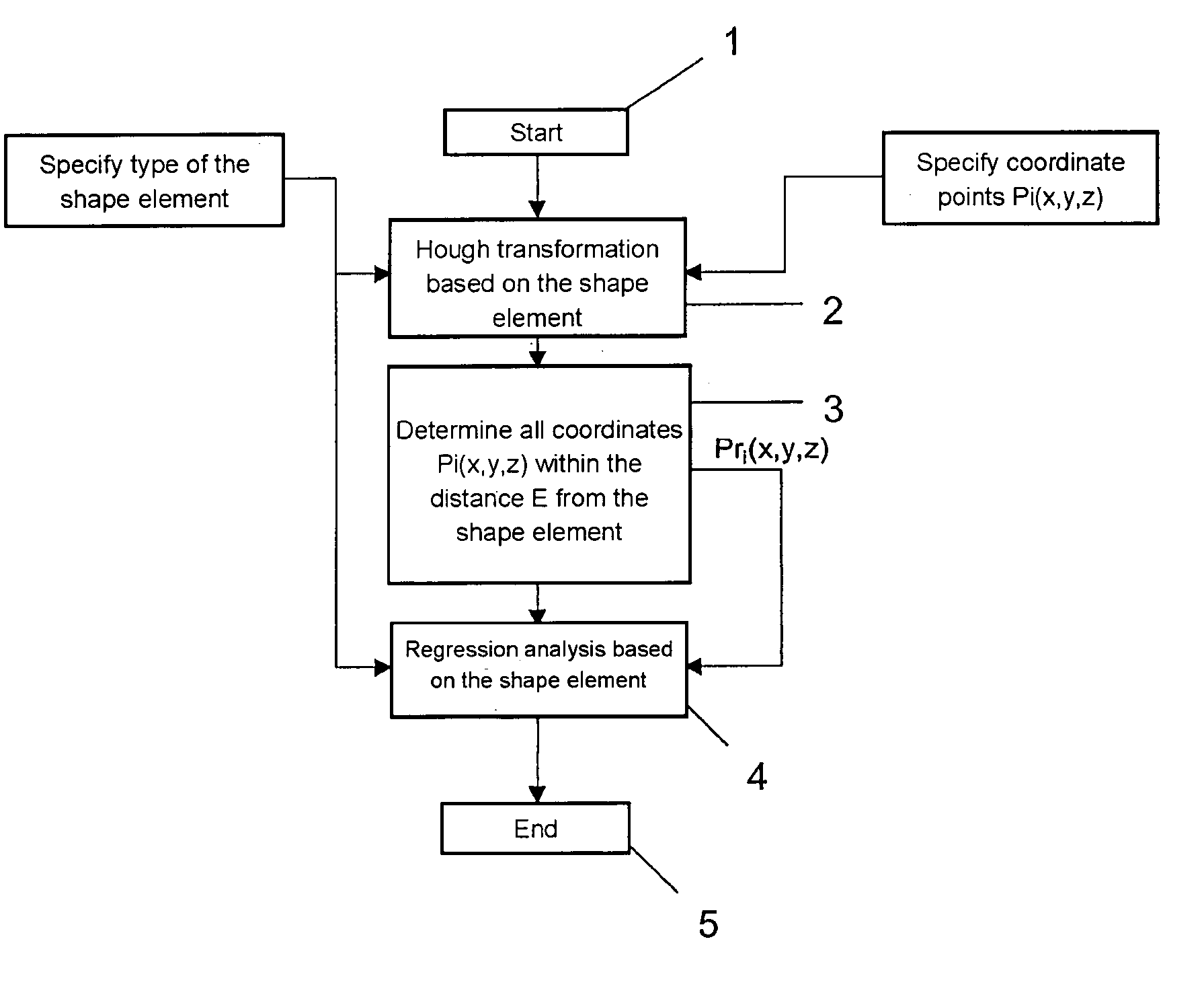
[0011] Embodiments of the present invention provide a method of analyzing measuring data comprising: inputting measuring data from a measuring device the measuring data comprising a set of data values representing features of an object; performing a recognition method on at least a subset of the data values for determining first parameters of a geometric shape element representing at least a portion of a feature of the object; eliminating outliers from the set of data values, the outliers having a distance from the shape element having the determined first parameters greater than a first threshold; and performing a first regression analysis on a set of remaining data values not including the outliers, for determining second parameters of the geometric shape element such that the shape element having the second parameters is a better representation of the portion of the at least one feature of the object than the shape element having the first parameters.
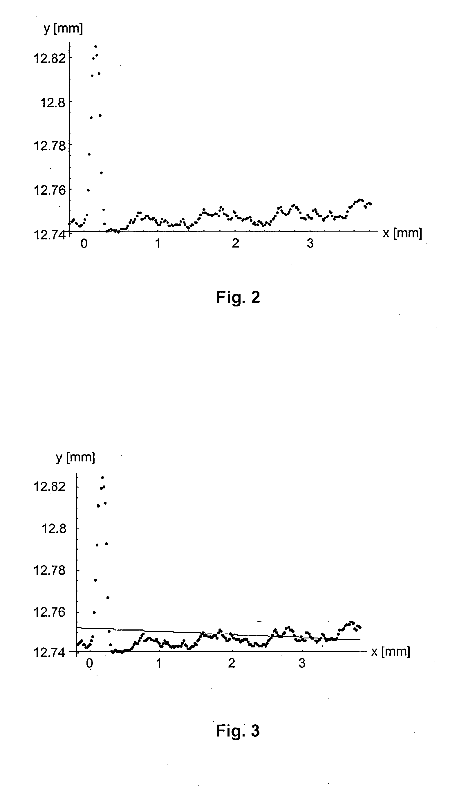
[0013] According to embodiments of the present invention, a recognition method is applied to the measuring data for identifying a geometric shape element represented by the disturbed measuring data. Thereafter, outliers of the measuring data and representing disturbances of the measuring data are eliminated, and the first regression analysis is performed on the remaining measuring data not including the outliers. A result of the regression analysis is a set of parameters of the geometric shape element coinciding with the desired feature of the object to a high accuracy. It has been found that the recognition method applied to the disturbed measuring data is well-suited for identifying the outliers such that the remaining measuring data not including the outliers form an improved basis for determining the parameters of the shape element by regression analysis.
[0024] It has been found that the above illustrated method is a robust method for identifying geometric shape elements representing a feature of an object imaged by the camera also in situations where significant disturbances are included in the image data.
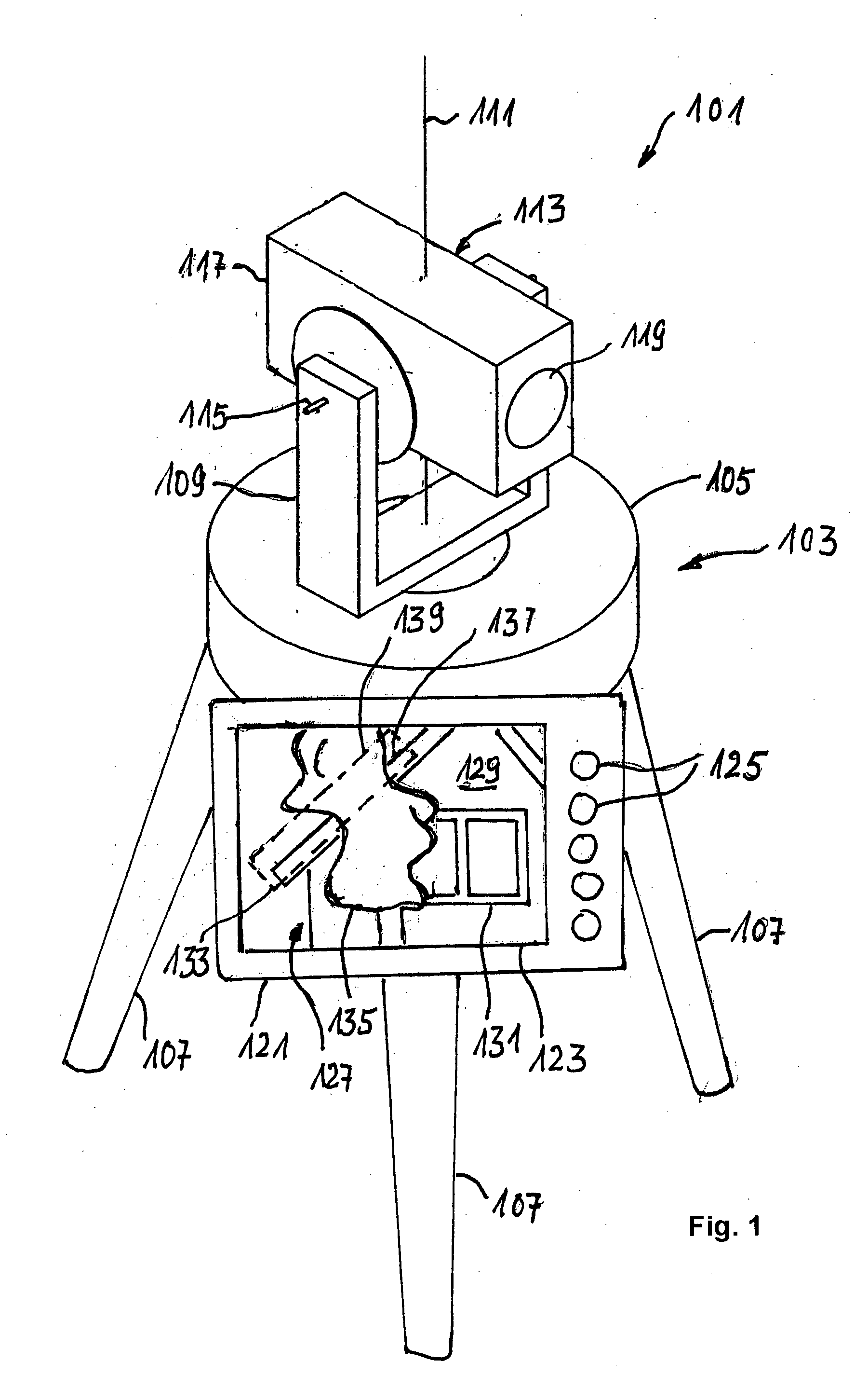
[0027] According to a further exemplary embodiment, the surveying apparatus further comprises a display for displaying an image represented by the image data. The apparatus may further comprise an input device for selecting a portion of the displayed image. The controller is then further configured to generate the measuring data subject to the analysis according to the above illustrated method from the image data representing the selected portion of the displayed image. A user may perform a short analysis of the displayed image and determine a portion of the image containing the target of interest of the surveying task, such as an edge of a building. By selecting the portion containing the target, it is possible to reduce an amount of data to be processed by the analyzing method.

Problems solved by technology

It has been found that the conventional methods of image processing may not always achieve a satisfactory measuring result.
The images detected by the camera are subject to disturbances due to varying lighting conditions.
Moreover, the object to be identified in the image may have complex structures due to textured surfaces and image backgrounds, and portions of the objects to be identified may be hidden by other objects, such as trees.
Therefore, a reliable and robust detection of object features is not always possible.

Method used


Image

  • Surveying apparatus and method of analyzing measuring data
  • Surveying apparatus and method of analyzing measuring data
  • Surveying apparatus and method of analyzing measuring data

Examples


Embodiment Construction

[0041] In the exemplary embodiments described below, components that are alike in function and structure are designated as far as possible by alike reference numerals. Therefore, to understand the features of the individual components of a specific embodiment, the descriptions of other embodiments and of the summary of the invention should be referred to.

[0042] The invention includes methods of filtering coordinate points in the calculation of shape elements with the aim to exclude such coordinates from the shape element calculation which can locally not be assigned to the expected ideal geometric shape.

[0043] The calculation of the shape of the object of measurement from a set of measuring data, such as coordinate points of the object surface that have been acquired by probing, is a well-known problem in coordinate measurement. The shape is described by ideal geometric substitute elements (briefly called shape elements), such as straight line, circle, ellipse, sphere, or cylinder...


PUM


Abstract

Embodiments of the invention relate to a method for minimizing the influence of disturbing signals during calculation of shape elements from coordinate points. An aim of the embodiments of the invention is to exclude the coordinates which are not to be locally assigned to the desired shaped element from the calculation of the shaped element. Said aim is achieved by combining compensation methods for calculating the desired type of shaped element with recognition methods for the same type of shaped element and using the recognition methods for filtering the coordinate points that are relevant for calculating the shaped element out of all input coordinate points.

Description

CROSS REFERENCE TO RELATED APPLICATIONS [0001] This application is a continuation-in-part of International Application No. PCT / EP2003 / 009996, with an international filing date of Sep. 9, 2003, which International Application was published by the International Bureau on Apr. 1, 2004, and which was not published in English, the entire contents of which are incorporated herein by reference. This application also claims the benefit of DE 102 42 852.2 filed on Sep. 14, 2002, the entire contents of which are incorporated herein by reference.BACKGROUND OF THE INVENTION [0002] 1. Field of the Invention [0003] The present invention relates to surveying instruments and methods of analyzing measuring data. [0004] 2. Brief Description of Related Art [0005] A conventional surveying apparatus, such as a total-station, a tacheometer, and a theodolite, comprise an optical system, such as a telescope, having a predetermined optical axis carried on a mounting structure such as a tripod. A user, while...

Claims


Application Information

Patent Timeline
Patent Type & Authority Applications(United States)
IPC IPC(8): G01B21/04G06T7/60G06V10/48
CPCG06K9/4633G01B21/045G06V10/48
Inventor USBECK, CHRISTIANBRUECKNER, PETERKUEHN, OLAFLINSS, GERHARD
Owner TRIMBLE JENA
Learn More