Capacitive sensor

a capacitive electrode and capacitive sensor technology, applied in the field of capacitive electrodes, can solve the problems of limiting battery life, inaccurate measurement, and ineffective protection of capacitive electrodes and electronic circuitry from hostile environmen

Active Publication Date: 2005-10-20
ANALOG DEVICES INC
View PDF14 Cites 74 Cited by
  • Summary
  • Abstract
  • Description
  • Claims
  • Application Information

AI Technical Summary

Benefits of technology

[0012] It is a further object of this invention to provide such a capacitive sensor which effectively protects the capacitive electrodes and the electronic circuitry from a hostile environment

Problems solved by technology

By comparison, conventional pressure sensors which utilize piezo-resistive elements to measure changes in resistance to determine pressure are less power efficient which limits battery life.
The openings allow unwanted contaminants to enter the cavity which affects the capacitance being measured which leads to inaccurate measurements and can destroy the sensor.
However, the sensor as disclosed in the '795 patent has a limited spacing between the capacitive plates on the order of about 0.5 to 2.5 mils, and hence cannot accommodate any signal processing circuitry (e.g., an integrated circuit die).
Hence, the design of the sensor

Method used


Image

  • Capacitive sensor
  • Capacitive sensor
  • Capacitive sensor

Examples


Embodiment Construction

[0049] Aside from the preferred embodiment or embodiments disclosed below, this invention is capable of other embodiments and of being practiced or being carried out in various ways. Thus, it is to be understood that the invention is not limited in its application to the details of construction and the arrangements of components set forth in the following description or illustrated in the drawings.

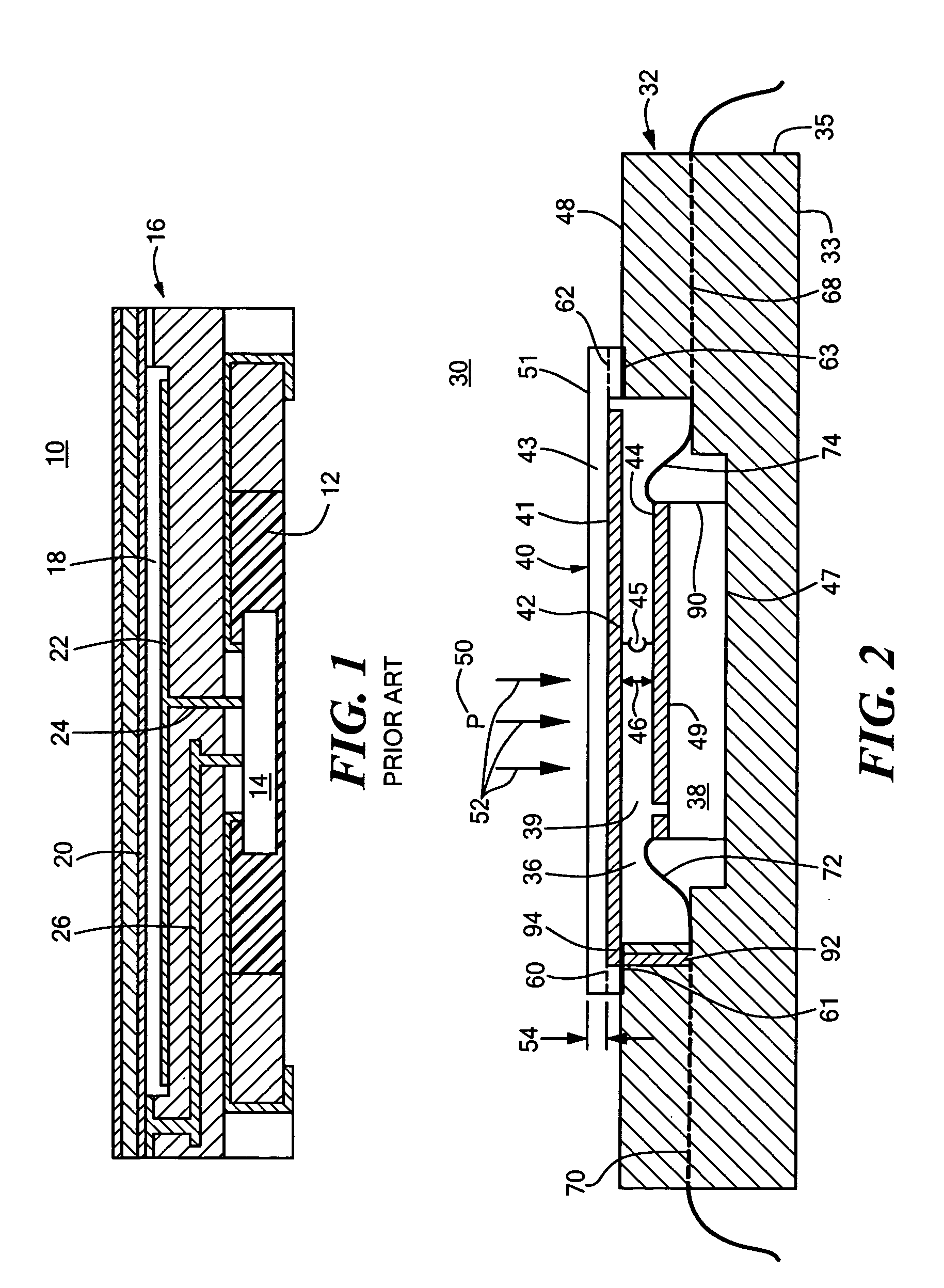
[0050] As discussed in the Background section above, conventional capacitive-type pressure sensors, such as conventional capacitive pressure sensor 10, FIG. 1, as disclosed in Japanese Patent Application No. 2002039893 cited supra, overcomes the problem associated with contaminants affecting the capacitive electrodes with hermetically sealed cavity 18. Hermetically sealed cavity 18 includes capacitive electrode plates 20 and 22 which form a capacitive measuring device within sealed cavity 18. Capacitive pressure sensor 10 also includes cavity 12 which accommodates die 14. Sensor 10 also i...


PUM


Abstract

A capacitive sensor including a housing having a hermetically sealed cavity, a plate in the cavity, a diaphragm forming a part of the cavity and spaced from the plate, a conductive layer on the first diaphragm, and a second conductive layer on the plate, the first and second conductive layers being the electrodes of a capacitor whose capacitance varies with the position of the diaphragm relative to the plate.

Description

RELATED APPLICATIONS [0001] This application claims benefit of U.S. Provisional Application No. 60 / 494,147, filed Aug. 11, 2003, entitled “Low Cost Pressure Sensor” incorporated by reference herein.FIELD OF THE INVENTION [0002] This invention relates generally to a capacitive sensor and more particularly to an improved capacitive sensor for measuring pressure. BACKGROUND OF THE INVENTION [0003] Pressure sensors for use in applications such as tire pressure monitoring systems and the like need to be inexpensive, resistant to hostile environments, and consume very little power. This is especially important in battery powered systems because the sensor and related electronic circuits may operate for an extended period of time on a single coin sized battery. [0004] By comparison, conventional pressure sensors which utilize piezo-resistive elements to measure changes in resistance to determine pressure are less power efficient which limits battery life. To overcome the problems associate...

Claims


Application Information

Patent Timeline
IPC IPC(8): G01LG01L9/00G01L9/12G01L13/02
CPCG01L9/0072G01L9/0073G01L9/0075G01L13/025H01L2224/48091H01L2924/3025H01L2924/00014H01L2924/00G01L19/0076
Inventor O'DOWD, JOHNMCCARTNEY, DAMIEN JOSEPHHUNT, WILLIAMHYNES, EAMONWYNNE, JOHN M.CROWLEY, PATRICKMARTIN, JOHN R.
Owner ANALOG DEVICES INC
Why Eureka
Try Eureka