Method for expansion injection molding

a technology of expansion injection and molding chamber, which is applied in the field of injection molding processes, can solve the problems of difficult control of foaming, the inability to completely fill the cavity with resin, and the almost complete unfoamed state of all molten resin, and achieves the effect of efficient manufacturing of lightweight plastic, good appearance and toughness

Active Publication Date: 2005-10-20
UBE MASCH CORP LTD
View PDF7 Cites 32 Cited by
  • Summary
  • Abstract
  • Description
  • Claims
  • Application Information

AI Technical Summary

Benefits of technology

[0019] The present invention has been made to solve the problems of the known techniques described above. It is an object of the present invention to provide an injection-foaming molding process for efficiently manuf

Problems solved by technology

Therefore, the foaming agent is partly decomposed by heat depending on the kind of the foaming agent and starts to foam in a trace amount; however, almost of all the molten resin remains in a substantially unfoamed state.
Furthermore, since the cavity volume is large, the cavity cannot be completely filled with the resin when there is employed a mold having a narrow portion (a portion having a large flow resistance) at a remote portion from the gate.
In this process, the control of foaming becomes difficult since the viscosity of the molten resin is increased due to a decrease in resin temperature, in addition to a prolonged cycle time for forming and the resulting lowered production efficiency.
Therefore, there is a problem in that cell nuclei formed in the resin-reserving section are not only mixed with an article to be formed in the next cycle but also foaming cannot be substantially controlled due to a increase in viscosity caused by a decrease in resin temperature when the injection time is prolonged.
However, in case of the injection-foaming molding process according to the above-mentioned conventional short shot process, there likely occurs such a phenomenon that the foaming agent contained in a molten resin is burst during injection of a molten resin containing a foaming agent into the cavity (this phenomenon is often called as a broken foam).
In the case of a formed article containing broken foams, there is a problem t

Method used


Image

  • Method for expansion injection molding
  • Method for expansion injection molding
  • Method for expansion injection molding

Examples


examples

[0233] The first embodiment is further described with examples. Molding conditions common to examples and comparative examples relating to this embodiment are as described below.

(1) Molding Material (Resin Used)

[0234] A material used is as follows: a resin material containing polypropylene (MFR is equal to 40 g per ten minutes) and 3% of a foaming agent masterbatch, dry-blended therewith, containing sodium hydrogen carbonate.

(2) Injection Molding Machine

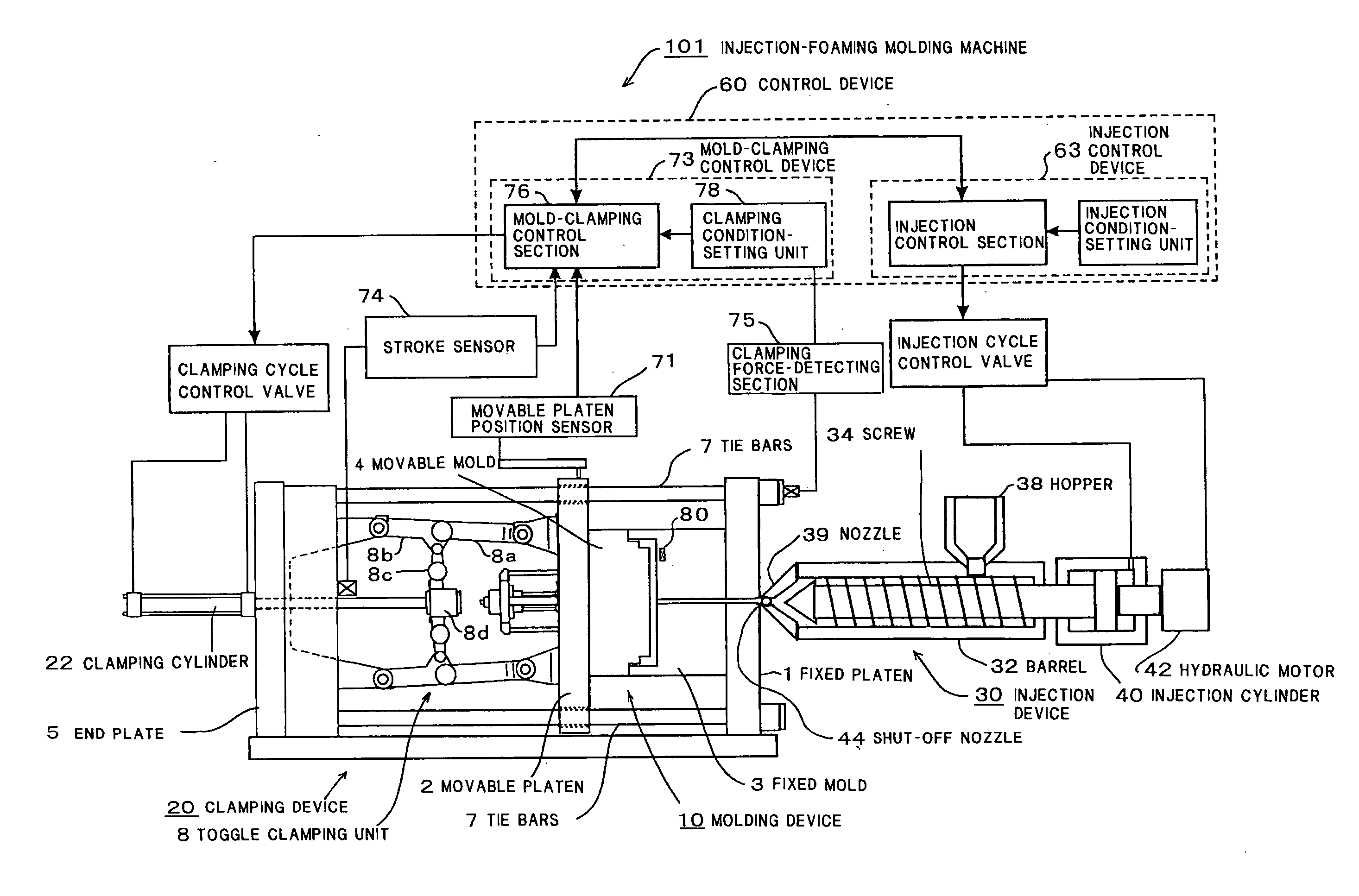
[0235] A machine used is as follows: an electric injection molding machine, Model MD350DP, manufactured by Ube Machinery Corporation, ltd., including a pneumatic needle shut-off nozzle.

(3) Mold

[0236] A mold used is as follows: a mold, having a size of 200 mm square, for a flat plate test was used. The mold has a gate structure in which a single direct gate is placed at a side of an article to be formed.

Molding Conditions of Example 1

[0237] Temperature of Resin for Molding: 200° C.

[0238] Temperature of Mold: 40° C.

[0239] ...

example 3

[0260] The mold was closed by moving a mold to a position for achieving an opening stroke of 10 mm and maintained in this state, and a molten resin was injected into a cavity of the mold. After the injection was completed, the mold was clamped at a clamping speed of 50 mm / sec with a clamping force of 1000 kN.

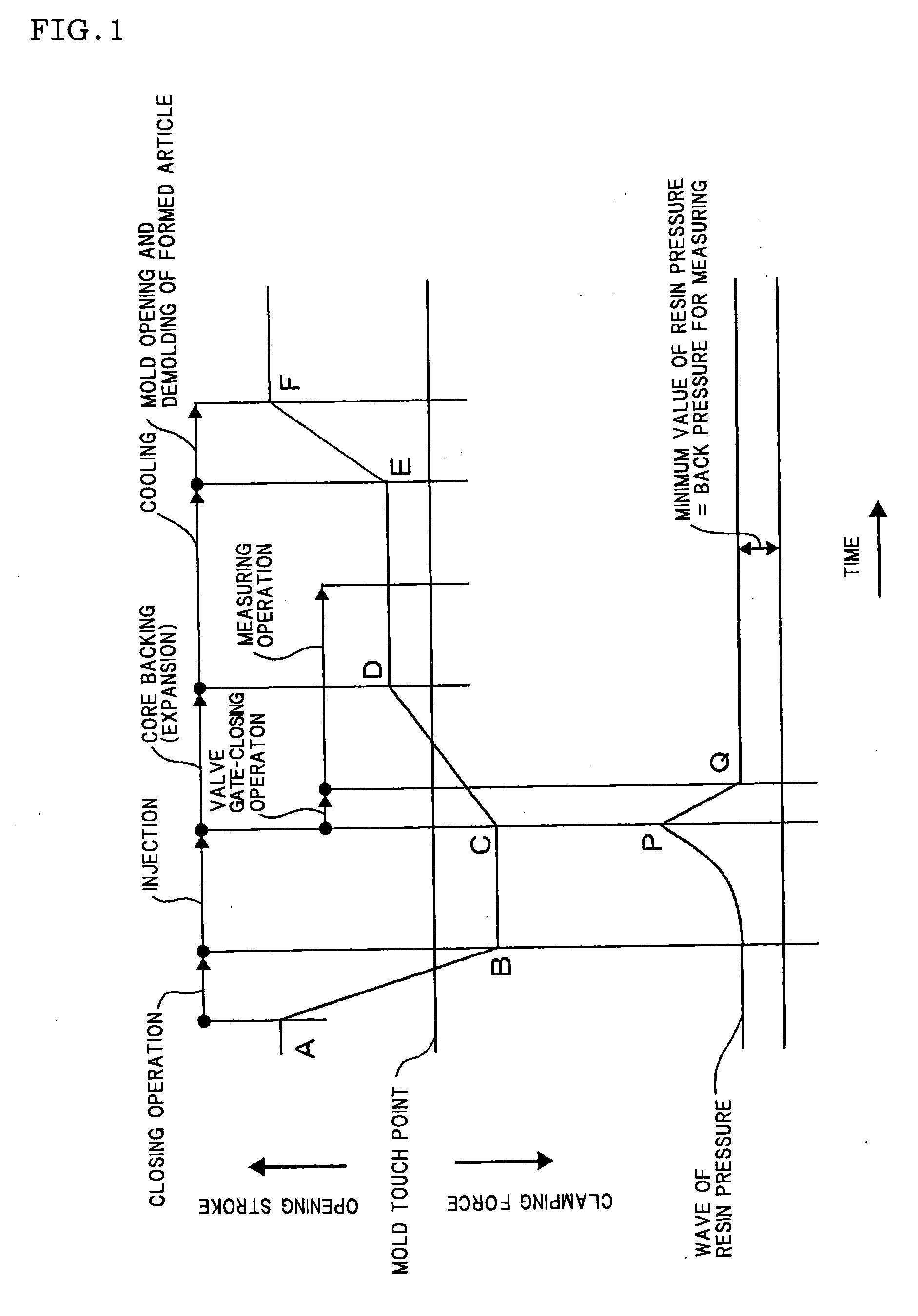
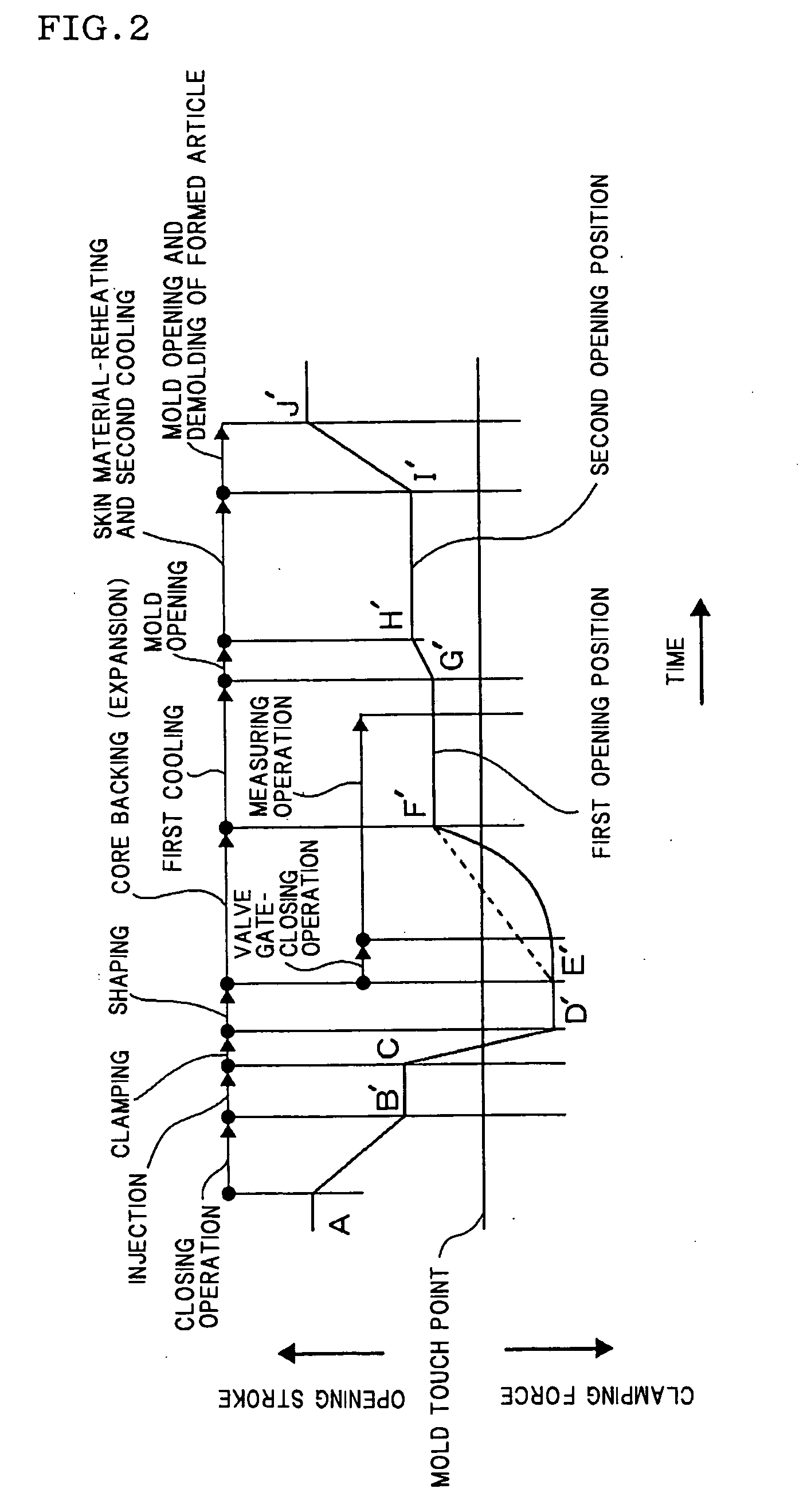
[0261] The temperature for molding the resin was set to 200° C., the temperature of the mold was set to 40° C., the injection speed was set to 150 mm / sec, the injection time was set to one second, and the injection pressure was set to 100 MPa. The mold was opened to allow the resin to foam (core backing) one second later after the mold was closed (the shaping time was set to one second).

[0262] The foaming magnification was set to two (the cavity clearance is 1.5 mm before the mold is opened and the opening stroke is 1.5 mm when the resin is allowed to foam; hence, a formed article has a thickness of 3 mm).

[0263] The mold was opened to allow the resin to foam (core pulling was...

example 4

[0265] The pressure in the resin-reserving section located at the front end of the screw was controlled during the period from the completion of injection to the start of charging in such a manner that “a pressure of 100 MPa applied to the resin-reserving section at the completion of the injection was reduced to 10 MPa to which the back pressure was preset and the pressure in the resin-reserving section was maintained at 10 MPa until the charging was started”. Other conditions were the same as those described in Example 3.


PUM

PropertyMeasurementUnit
Lengthaaaaaaaaaa
Timeaaaaaaaaaa
Lengthaaaaaaaaaa

Abstract

An injection-foaming molding process for manufacturing a formed article by injecting a molten resin containing a foaming agent into a cavity of a mold being retained in an openable state and then expanding the cavity by opening the mold to allow the resin to foam includes: i) a step of discontinuing a cavity of a mold from a resin-reserving section located at front end of a screw immediately after the completion of injection of a molten resin containing an expandable resin into the mold cavity; and ii) a step of keeping the resin-reserving section under pressure at least equal to back pressure for charging during a period from the completion of injection to start of charging the molten resin containing the expandable resin for next shot, decreasing pressure in the resin-reserving section to back pressure for charging, and then starting the charging. According to the process, a molding cycle can be shortened and a lightweight formed article by foaming having high rigidity and good appearance can be obtained.

Description

TECHNICAL FIELD [0001] The present invention relates to injection molding processes for expandable plastic compositions. More particularly, it relates to an injection-foaming molding process for manufacturing a lightweight plastic formed article by foaming having a fine and uniform highly foamed structure, high thermal insulation, and high rigidity. A first aspect of the present invention relates to an injection-foaming molding process for manufacturing a formed plastic article by foaming having a surface of densely foamed structure. A second aspect of the present invention relates to an injection-foaming molding process for manufacturing a plastic formed article having a skin material having a surface layer of a high quality, and particularly relates to an injection compression type forming process under the conditions that a resin is injected into a mold which is opened with employment of a relatively thick surface material. A third aspect of the present invention relates to an in...

Claims


Application Information

Patent Timeline
IPC IPC(8): B29C44/58B29C44/60
CPCB29C44/60B29C44/586B29C45/46B29C45/76B29C45/52
Inventor TAKATORI, HIROYUKIOKAMOTO, AKIOYAMAMOTO, NAOTOSHIMIZU, FUMIHIKO
Owner UBE MASCH CORP LTD
Why Eureka
Try Eureka