Apparatus and method of balancing a shaft

a technology of aircraft turbine engine and shaft, applied in the direction of propellers, propulsive elements, water-acting propulsive elements, etc., can solve the problems of shaft imbalance, mass imbalance, shaft imbalance, etc., and achieve the effect of reducing the manufacturing cost of the aircraft engin

Active Publication Date: 2005-10-20
PRATT & WHITNEY CANADA CORP
View PDF24 Cites 34 Cited by
  • Summary
  • Abstract
  • Description
  • Claims
  • Application Information

AI Technical Summary

Benefits of technology

[0013] Another advantage of the present invention lies in that standard fasteners rather than specially configured balancing weights are used to balance the shaft of the aircraft engine, resulting in reduced manufacturing expenses of the aircraft engine. This advantage is even more significant when the present invention is applied to small aircraft turbine engines.
[0014] Other features and advantages of the present invention will be better understood with reference to a preferred embodiment described hereinafter.

Problems solved by technology

The main drive shafts of aircraft gas turbine engines are subject to mass imbalance due to manufacturing variations.
Shaft imbalance is characterized by a magnitude of imbalance and an angular direction of imbalance.
Further balance adjustment however, is normally difficult due to the inaccessibility of the rotating parts and, quite frequently, the unbalance is so severe that it is necessary to strip the turbine engines for rebalancing.

Method used


Image

  • Apparatus and method of balancing a shaft
  • Apparatus and method of balancing a shaft
  • Apparatus and method of balancing a shaft

Examples


Embodiment Construction

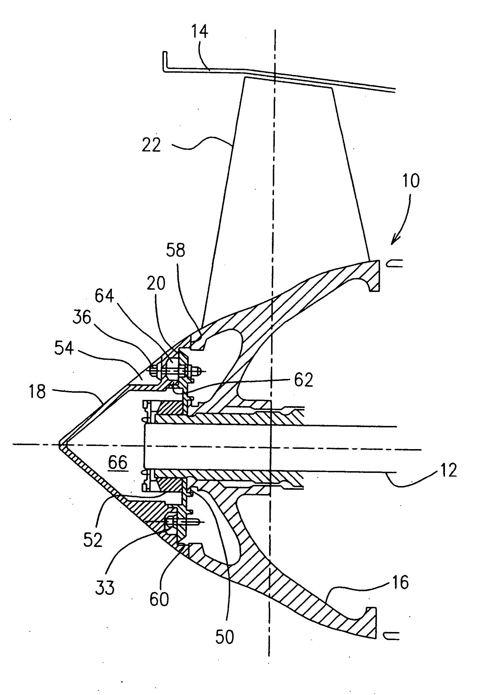
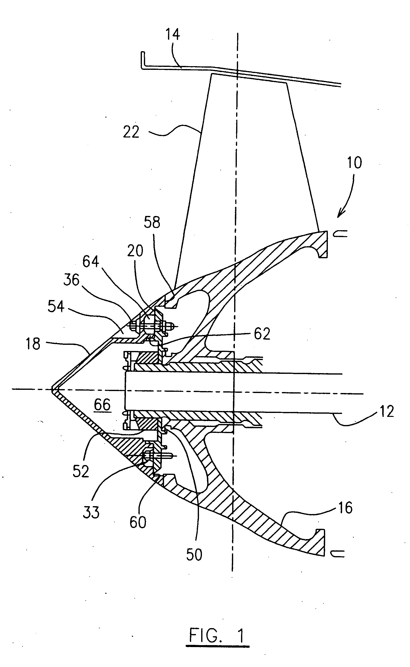
[0022] Referring to the drawings, particularly FIGS. 1 and 2, an aircraft turbine engine generally indicated by numeral 10 includes a main shaft 12 rotatably supported within an engine casing 14 and being driven by a turbine rotor (not shown) of the engine. A fan integrated blade rotor (IBR) assembly 16 is mounted to a forward end of the main shaft 12 to be driven in rotation together therewith. A nose cone 18 is mounted to the forward end of the main shaft 12 by means of a mounting plate 20 such that an annular airflow inlet is defined at the front opening 22 of the engine casing 14, between the engine casing 14 and the fan IBR assembly 16 together with the nose cone 18. The nose cone 18 at its rear side defines a central cavity 66 therein to accommodate the forward end of the main shaft 12 and, the fan retaining nut 52 engaged with the forward end of the main shaft 12.

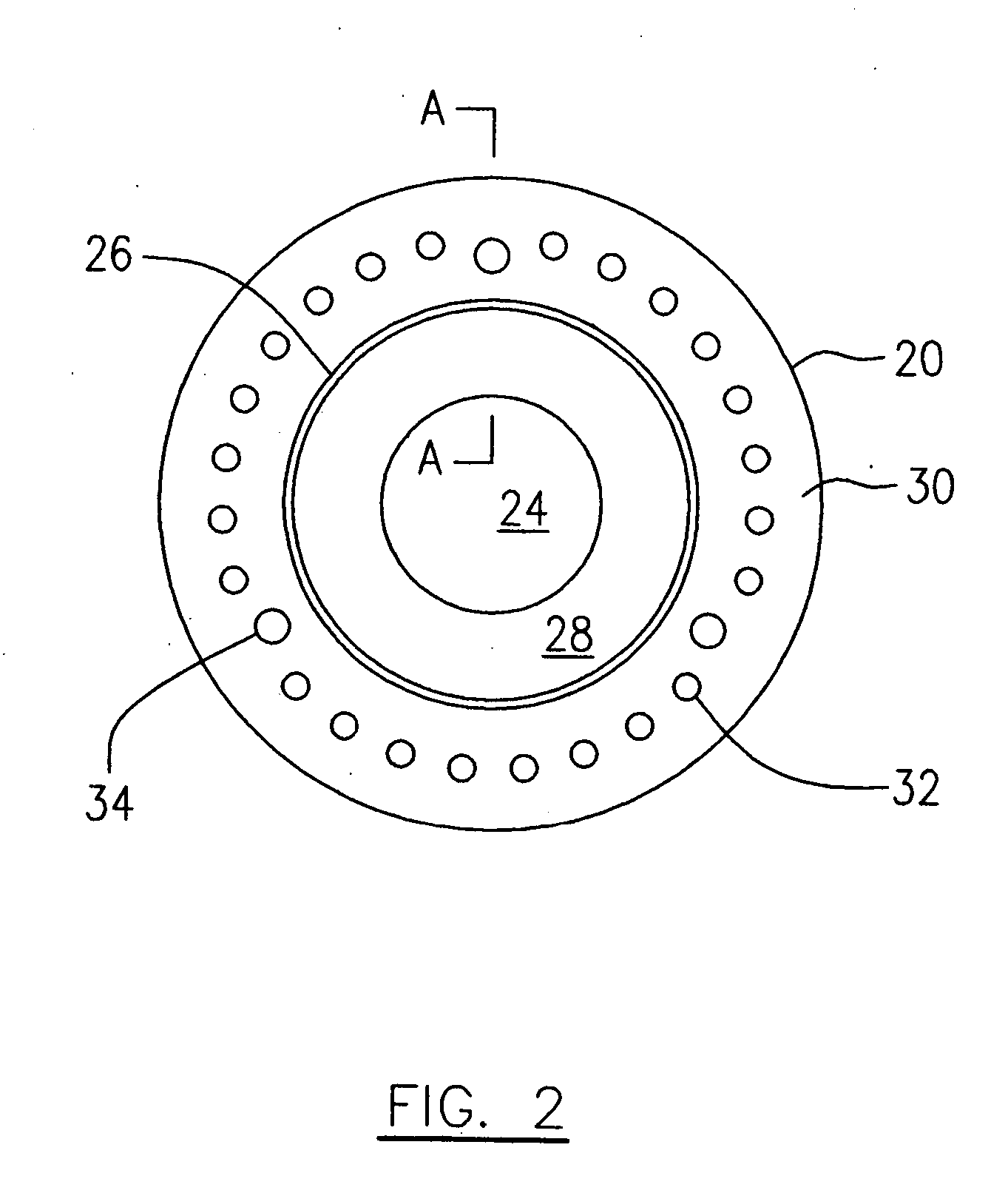
[0023] Referring to FIGS. 1, 2 and 3, the mounting plate 20 is a round plate preferably made of a turned steel, h...


PUM


Abstract

An apparatus for balancing a shaft of an aircraft engine preferably includes a plate and the use of standard fasteners. The plate provides mounting for nose cone, and the balancing apparatus may be accessed from the front of the assembled engine.

Description

FIELD OF THE INVENTION [0001] The present invention generally relates to a balancing apparatus and method, and more particularly to an apparatus and method for balancing a shaft of an aircraft turbine engine. BACKGROUND OF THE INVENTION [0002] The main drive shafts of aircraft gas turbine engines are subject to mass imbalance due to manufacturing variations. The shafts must be balanced prior to assembly in the engine in order to reduce shaft vibration during engine operation. [0003] Shaft imbalance is characterized by a magnitude of imbalance and an angular direction of imbalance. The magnitude of imbalance caused by an eccentric rotating mass, is a function of the weight of the mass and the radial distance of the mass from the axis of rotation. The angular direction of imbalance is determined by the angular position of the eccentric mass relative to an arbitrary reference direction. [0004] Due to the subsequent operations of an aircraft turbine engine assembly, there is often a nee...

Claims


Application Information

Patent Timeline
Patent Type & Authority Applications(United States)
IPC IPC(8): F01D5/02F02C7/20F16F15/22F16F15/32F16F15/34G01M1/32H02K5/16H02K7/08
CPCF01D5/027F02K3/04Y02T50/671G01M1/32F16F15/34Y02T50/60
Inventor ROCKARTS, SEAN ANDREBARNETT, BARRY
Owner PRATT & WHITNEY CANADA CORP
Why Eureka
Try Eureka