Delay locked loop

a delay lock and loop technology, applied in the field of delay lock loops, can solve the problems of limiting unable to perform logic verification relating to the dll or defect analysis in the wafer level, and affecting the operation of the low voltage high speed operation, etc., to achieve the effect of low frequency operation

Inactive Publication Date: 2005-10-20
INTELLECTUAL DISCOVERY CO LTD
View PDF5 Cites 13 Cited by
  • Summary
  • Abstract
  • Description
  • Claims
  • Application Information

AI Technical Summary

Benefits of technology

[0011] The present invention is directed to a delay locked loop which can perform a low frequency operation in a wafer level, by reducing a period of an external clock to a half in a chip through a f

Problems solved by technology

When an external clock is used inside the system or circuit, a time delay (clock skew) occurs by inside circuits.
However, the conventional arts satisfy only part of the factors, or restrict the low voltage high speed operation.
It is thus im

Method used


Image

  • Delay locked loop
  • Delay locked loop
  • Delay locked loop

Examples


Embodiment Construction

[0017] A delay locked loop (DLL) in accordance with a preferred embodiment of the present invention will now be described in detail with reference to the accompanying drawings. Wherever possible, the same reference numerals will be used throughout the drawings and the description to refer to the same or like parts.

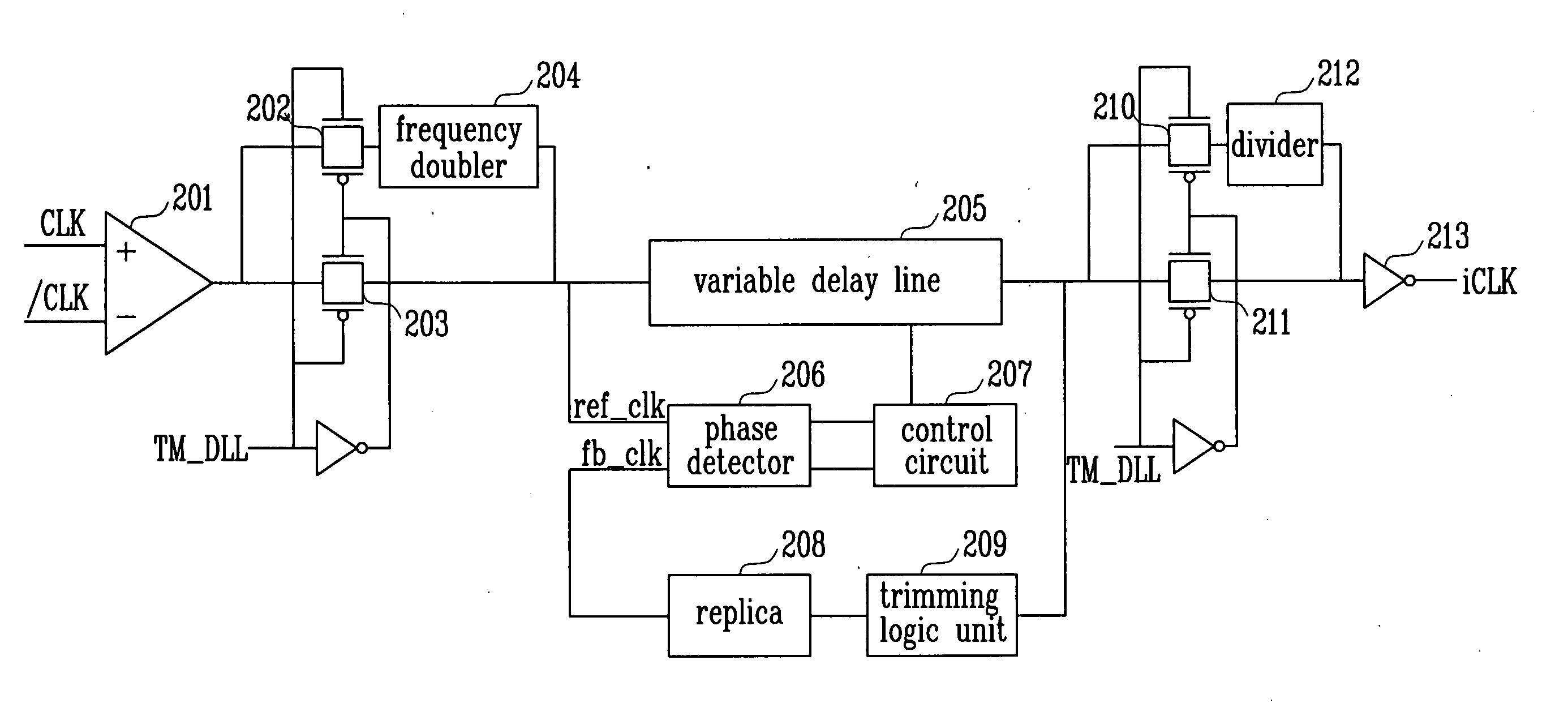
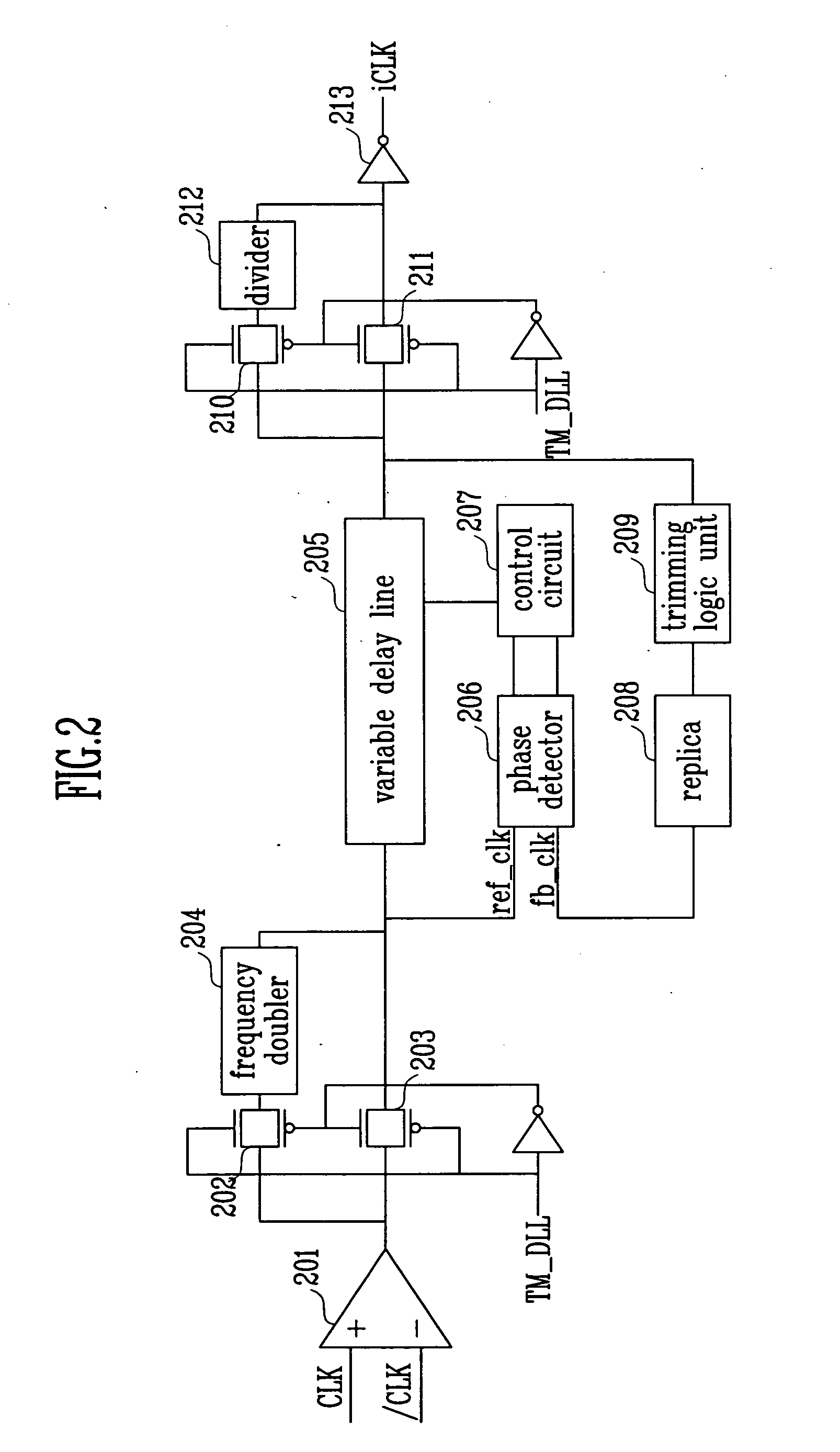
[0018]FIG. 2 is a block diagram illustrating the DLL in accordance with the preferred embodiment of the present invention.

[0019] An input buffer 201 buffers external clocks CLK and / CLK. In a test mode, a test mode signal TM_DLL has a high state, and thus a transmission gate 202 is turned on. In the other modes, the test mode signal TM_DLL maintains a low state, and thus a transmission gate 203 is turned on.

[0020] The signal from the transmission gate 202 is increased to, for example, a double frequency by the frequency doubler 204. The output from the frequency doubler 204 or the signal from the transmission gate 203 is transmitted to the variable delay line 205. The v...


PUM

PropertyMeasurementUnit
Poweraaaaaaaaaa
Frequencyaaaaaaaaaa

Abstract

The present invention discloses a delay locked loop including: a frequency doubler for increasing the output frequency from an input buffer for buffering a clock; a variable delay line for delaying the output from the frequency doubler; a divider for restoring the output frequency from the variable delay line to the frequency of the clock by dividing the output frequency; an output buffer for buffering the output from the divider; a replica for delaying the output from the variable delay line; a phase detector for detecting a phase difference between the output from the replica and the output from the frequency doubler; and a control circuit for determining a delay amount of the variable delay line according to the output from the phase detector.

Description

[0001] This application relies for priority upon Korean Patent Application No. 2004-0027087 filed on Apr. 20, 2004, the contents of which are herein incorporated by reference in their entirety. BACKGROUND [0002] 1. Field of the Invention [0003] The present invention relates to a delay locked loop (DLL), and more particularly to, a DLL which can remove a skew of a clock and an output data in a read operation of a double data rate synchronous DRAM (DDR SDRAM). [0004] 2. Discussion of Related Art [0005] In general, a clock is used as a reference for adjusting an operational timing in a system or circuit, and also used to perform a faster operation without errors. When an external clock is used inside the system or circuit, a time delay (clock skew) occurs by inside circuits. A DLL compensates for the time delay, so that an internal clock can have the same phase as that of the external clock. [0006] The essential factors of the DLL include a small area, a small jitter and a fast locking...

Claims


Application Information

Patent Timeline
IPC IPC(8): G11C8/00H03K5/00H03K5/19H03L7/081
CPCH03K2005/00058H03L7/0812H03K2005/00156H03L7/0816B29C43/02E01B11/04E01B11/54
Inventor CHO, YONG DEOK
Owner INTELLECTUAL DISCOVERY CO LTD
Why Eureka
Try Eureka