Low-noise, fast-settling bias circuit and method

a bias circuit and fast-settling technology, applied in the field of bias circuits, can solve the problems of long time until the settling time, the proportional settling time of the lpfs, and the limited noise performance of the bias circui

Active Publication Date: 2005-10-20
AVAGO TECH INT SALES PTE LTD
View PDF3 Cites 26 Cited by
  • Summary
  • Abstract
  • Description
  • Claims
  • Application Information

AI Technical Summary

Benefits of technology

[0008] Embodiments of the invention provide a new bias circuit and method that provide a quick settling time in contrast to conventional LPFs.

Problems solved by technology

However, the noise performance of these circuits can be limited by noise contributed by the bias circuits.
However, a disadvantage of the LPFs is that the settling time of the LPFs is proportional to the product of their resistance and capacitance.
Accordingly, the stronger the LPF, the longer it will take for the LPF to settle, which translates into a longer time until the bias current or voltage can be used.

Method used


Image

  • Low-noise, fast-settling bias circuit and method
  • Low-noise, fast-settling bias circuit and method
  • Low-noise, fast-settling bias circuit and method

Examples


Embodiment Construction

[0016] The following description is provided to enable any person having ordinary skill in the art to make and use the invention, and is provided in the context of a particular application and its requirements. Various modifications to the embodiments will be readily apparent to those skilled in the art, and the generic principles defined herein may be applied to other embodiments and applications without departing from the spirit and scope of the invention. Thus, the present invention is not intended to be limited to the embodiments shown, but is to be accorded the widest scope consistent with the principles, features and teachings disclosed herein.

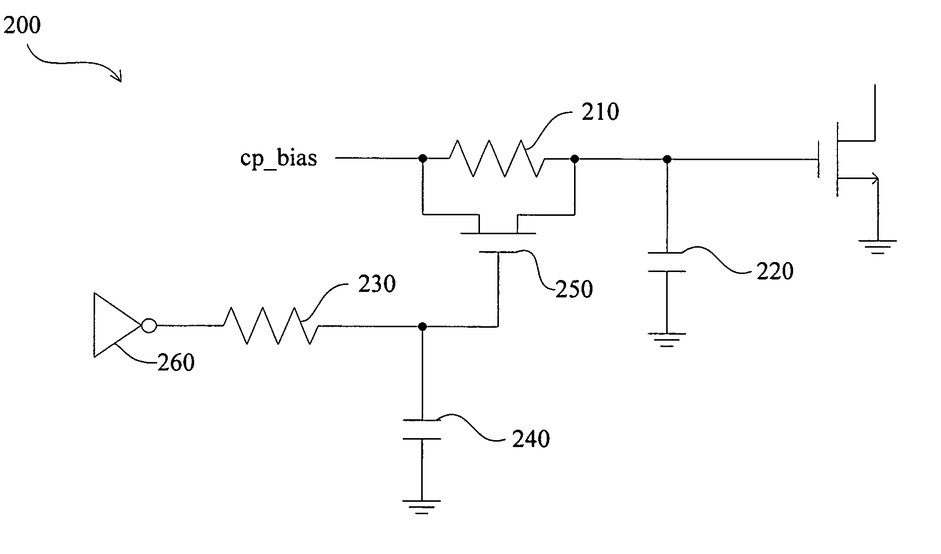
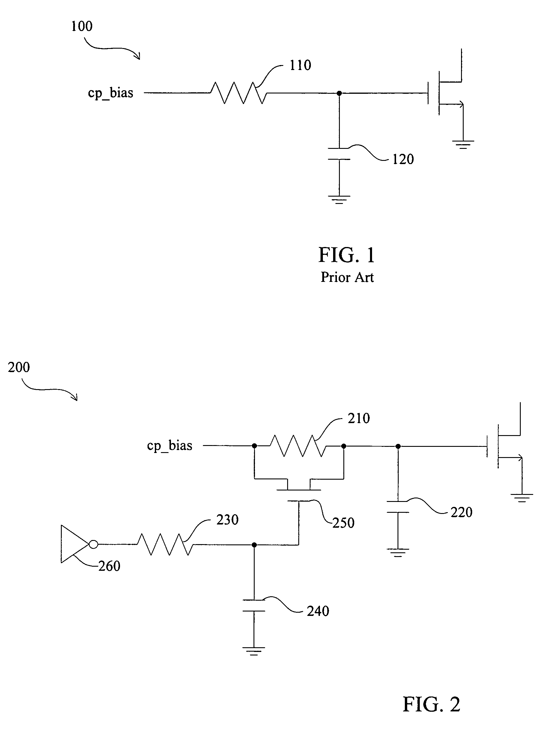
[0017]FIG. 2 is a block diagram illustrating a bias circuit 200 according to an embodiment of the invention. The bias circuit 200 includes a first LPF comprising a resistor 210 and a capacitor 220 and a second LPF comprising a resistor 230 and a capacitor 240. The second LPF is separated from the first LPF via a switch 250. Also communi...


PUM


Abstract

A low-noise, fast-settling bias circuit includes a first and a second low pass filter, such as RC filters. The second filter initially shorts out a resistor of the first filter with a switch (set to low impedance) in parallel. Accordingly, a capacitor of the first filter quickly charges up to the same voltage as the input bias voltage. As the second filter charges up, the switch slowly shuts off (high impedance). By this time, since the capacitor of the first filter has charged to the same voltage as the bias voltage, a large RC formed by the resistor of the first filter and the capacitor of the first filter is available to provide filtering for the desired bias current.

Description

BACKGROUND [0001] 1. Technical Field [0002] This invention relates generally to bias circuits, and more particularly, but not exclusively, to low-noise bias circuits that have a fast settling time. [0003] 2. Description of the Related Art [0004] Bias circuits generates a steady constant bias currents or bias voltages that presets the operating threshold or operating point of a circuit or device, such as a transistor, diode, or magnetic amplifier. Bias circuits can also be used for circuits such as voltage-controlled oscillators (VCOs) and charge pumps. However, the noise performance of these circuits can be limited by noise contributed by the bias circuits. [0005] In order to reduce noise in the bias circuit that might negatively effect other circuits, low pass filters (LPFs), such as resistor-capacitor (RC) filters are introduced into the bias circuit. For example, as shown in FIG. 1, a conventional bias circuit 100 includes a resistor 110 and a capacitor 120 that in combination fo...

Claims


Application Information

Patent Timeline
Patent Type & Authority Applications(United States)
IPC IPC(8): H03B1/00H03F1/26H03F1/30H03F3/14
CPCH03F1/305H03F1/26
Inventor WU, STEPHEN
Owner AVAGO TECH INT SALES PTE LTD
Why Eureka
Try Eureka