Jitter generator

a jitter generator and generator technology, applied in the direction of electrical equipment, pulse automatic control, etc., can solve the problems of poor phase noise characteristic and deterioration in accuracy

Inactive Publication Date: 2005-10-20
YOKOGAWA ELECTRIC CORP
View PDF2 Cites 26 Cited by
  • Summary
  • Abstract
  • Description
  • Claims
  • Application Information

AI Technical Summary

Benefits of technology

[0030] Also, in the jitter generator as claimed in one of claims 1 to 4, the phase signal generator includes a digital signal processor that calculates digital data of I(t) and Q(t) signals from the modulation signal at a high speed, and a digital / analog converter that converts a calculation output from the digital signal processor to an analog signal, and the phase signal generator outputs I(t) and Q(t) (claim 10).
[0031] Moreover, in the jitter generator as claimed in one of claims 5 to 10, a low-pass filter is provided downstream from the digital / analog converter.

Problems solved by technology

If the phase noise is large, a jitter due to the noise itself occurs and the original phase modulation becomes unstable, leading to deterioration in the accuracy.
Therefore, because of its nature, the phase noise characteristic is poorer than that of the reference signal.

Method used


Image

  • Jitter generator
  • Jitter generator
  • Jitter generator

Examples


Embodiment Construction

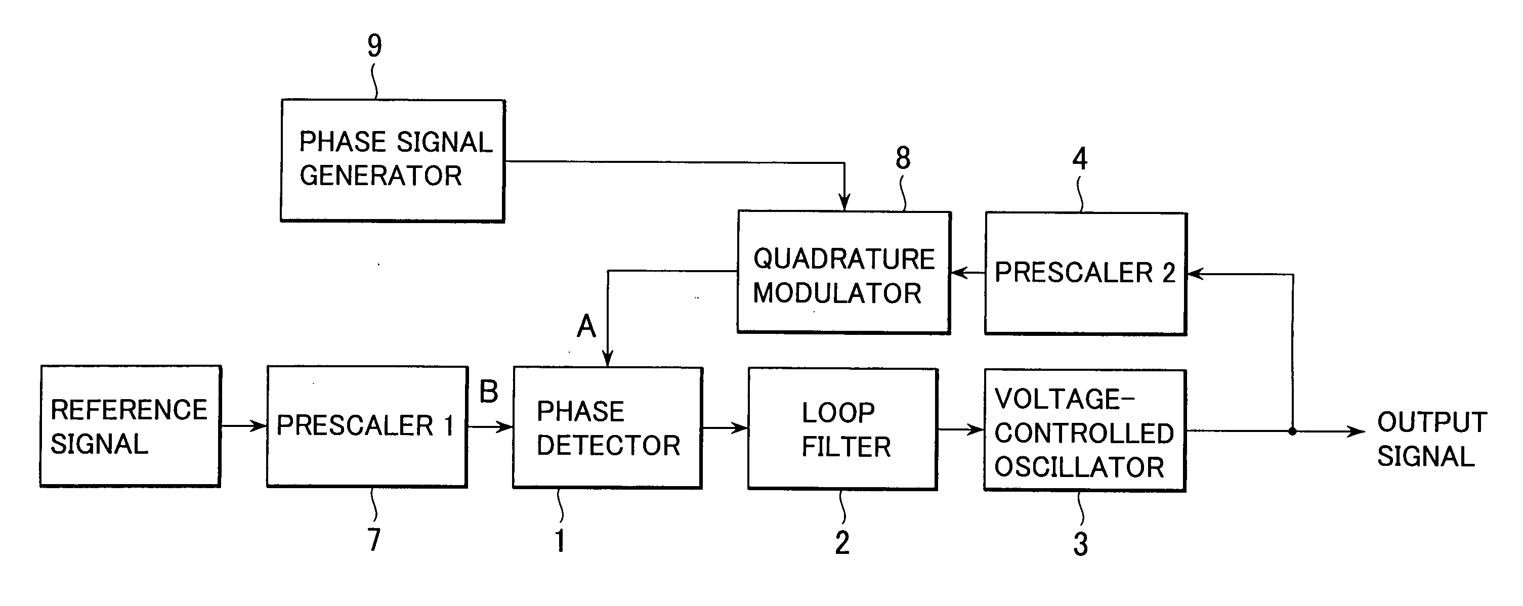
[0047]FIG. 1 is a view showing a fundamental structure of a jitter generator (phase modulator) according to this invention.

[0048] In FIG. 1, a phase detector denoted by 1, a loop filter denoted by 2, a voltage-controlled oscillator denoted by 3 and a second prescaler 4 form a PLL circuit.

[0049] In this invention, a quadrature modulator 8 is inserted into a feedback circuit part of PLL (that is, output side of the second prescaler 4). A modulated signal is provided to the phase detector and an output signal (phase-modulated signal) with a jitter added to a reference signal, which is an input, is acquired. However, when a dividing value of the second prescaler 4 is N, the output frequency and the jitter become an N value.

[0050] A first prescaler (prescaler 1) denoted by 7, arranged upstream from the phase detector, is optional and it is inserted when necessary.

[0051] In this case, since the PLL operates in such a manner that a quadrature modulation output A and an output B of the ...


PUM


Abstract

In a jitter generator (phase modulator), worsening of phase noise is restrained and phase modulation accuracy is improved, and the phase modulation accuracy is improved by preventing a change in the detection sensitivity of the phase detector, if any, from affecting a change in the phase modulation index. Also, phase modulation is made possible without lowering the phase modulation accuracy even when an input phase signal increases. In a jitter generator using a PLL circuit, a quadrature modulator to which a modulation signal from a phase signal generator is provided is inserted to an input stage of a phase detector that constitutes the PLL circuit. In addition to this, an overflow detector that detects an overflow on an upper limit side or lower limit side of an analog/digital converter, a control unit that outputs a value for an effective region of the analog/digital converter on the basis of an output of the overflow detector, a digital/analog converter that coverts an output of the control unit to an analog signal, and an adder that adds an output of the digital/analog converter to the modulation signal, are provided.

Description

BACKGROUND OF THE INVENTION [0001] 1. Field of the Invention [0002] This invention relates to a jitter generator that generates a jitter (that is, performs phase modulation) in a PLL system by using an quadrature modulator circuit. [0003] 2. Description of the Related Art [0004] Conventionally, it is common to use a PLL (phase-locked loop) for generating a jitter (that is, performing phase modulation) in an analog system. [0005]FIG. 15 shows a structure of a conventional jitter generator. [0006] In FIG. 15, a phase detector denoted by 1, a loop filter denoted by 2, a voltage-controlled oscillator denoted by 3 and a second prescaler (prescaler 2) denoted by 4 form a PLL circuit. [0007] As an adder 5 is additionally provided downstream from the phase detector 1 of the PLL circuit and a signal generated by a phase signal generator 6 is added by the adder 5, phase modulation is performed on a voltage-controlled oscillator output and an output signal (phase-modulated output signal) with ...

Claims


Application Information

Patent Timeline
Patent Type & Authority Applications(United States)
IPC IPC(8): H03B28/00H03L7/00
CPCH03B28/00
Inventor AKAHORI, HIROSHIMAEDA, MINORU
Owner YOKOGAWA ELECTRIC CORP
Why Eureka
Try Eureka