Apparatus for and method of forming image using oscillation mirror

a technology of oscillation mirror and image forming apparatus, which is applied in the direction of electrographic process apparatus, printing, instruments, etc., can solve the problems of deterioration of latent image carrier, halting of the deflector, and reducing the amplitude value of the pivoting oscillation mirror

Inactive Publication Date: 2005-10-20
SEIKO EPSON CORP
View PDF13 Cites 7 Cited by
  • Summary
  • Abstract
  • Description
  • Claims
  • Application Information

AI Technical Summary

Benefits of technology

[0016] A primary object of the present invention is to provide an image forming apparatus and an image forming method with which it is possible

Problems solved by technology

However, since the deflector operates after emission of the light beam from the light source, the deflector remains in a halt from turning on of the light source until the start of oscillations of the deflector.
This keeps exposing one point on the latent image carrier to irradiation with the light beam, causing a problem of deterioration of the latent image carrier.
Further, there is another problem described below when a resonant-type oscillation mirror is used as the deflector, owing to the structure and operation of the deflector.
Due to this, when an external factor such as an environment of use, a difference among individual oscillation mirrors or the like gives rise to a disagreement between the resonant freque

Method used


Image

  • Apparatus for and method of forming image using oscillation mirror
  • Apparatus for and method of forming image using oscillation mirror
  • Apparatus for and method of forming image using oscillation mirror

Examples


first embodiment

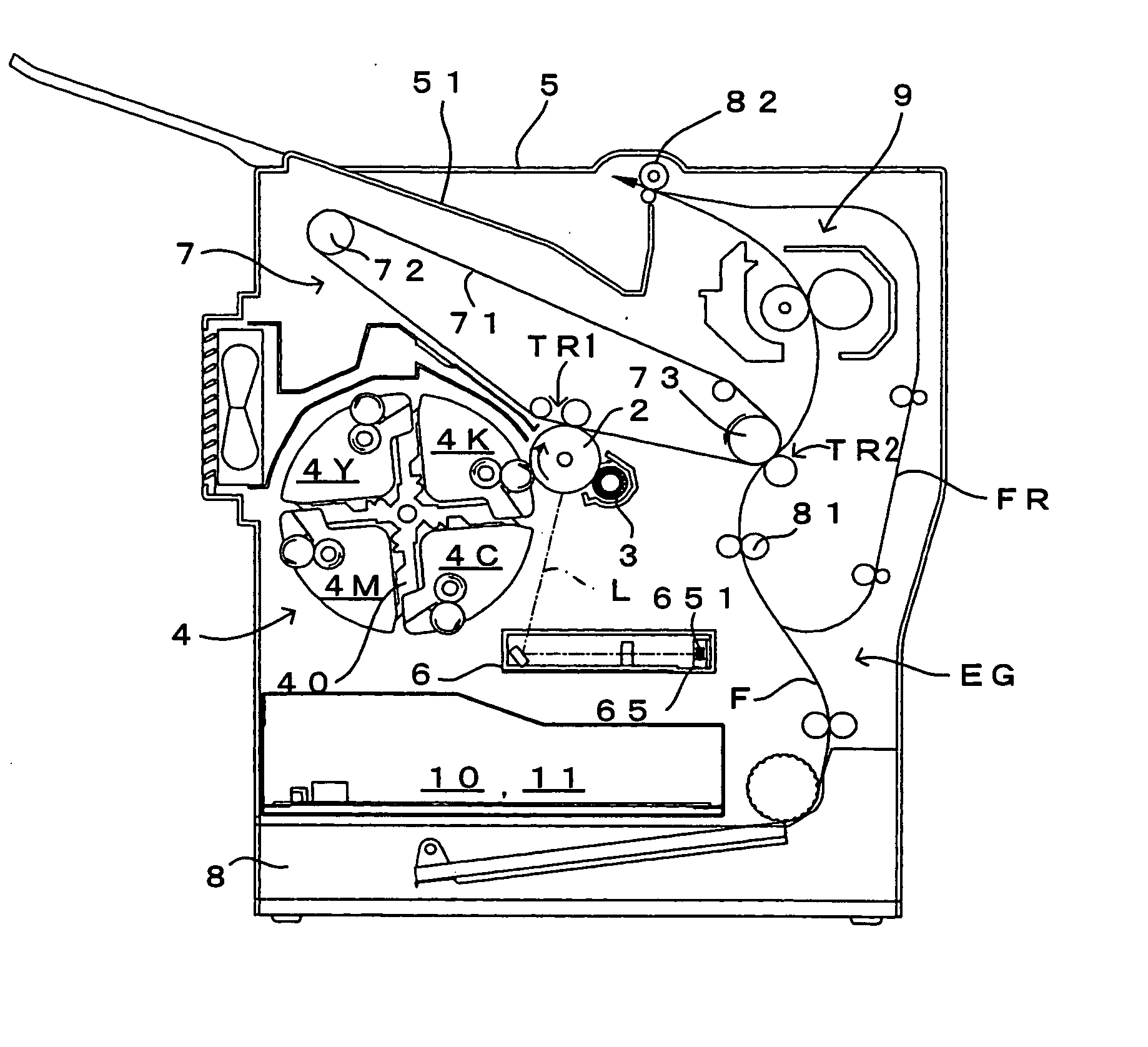
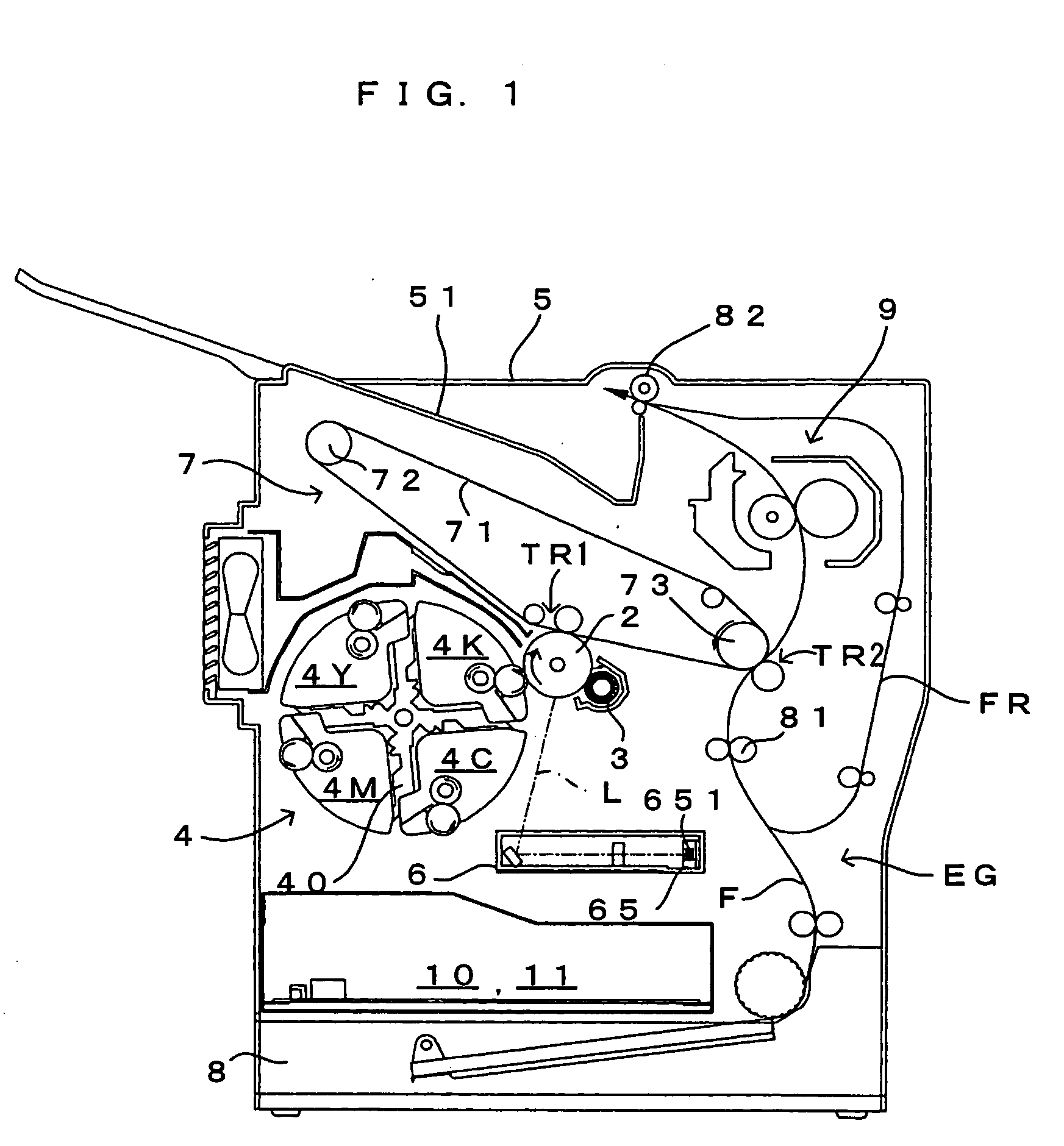
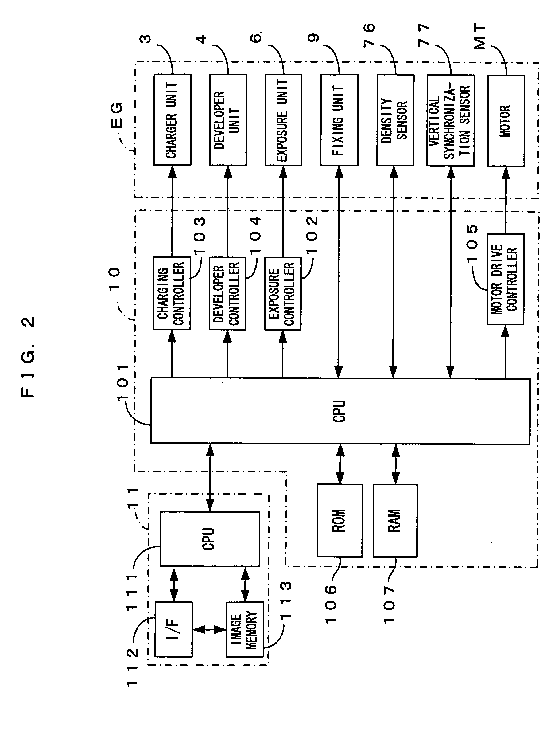
[0043]FIG. 1 is a drawing which shows an image forming apparatus according to the present invention. FIG. 2 is a block diagram which shows the electric structure of the image forming apparatus which is shown in FIG. 1. This image forming apparatus is a color printer of the so-called 4-cycle type. In this image forming apparatus, when a print command is fed to a main controller 11 from an external apparatus such as a host computer in response to a user's image formation request, an engine controller 10 controls respective portions of an engine part EG in accordance with the print command received from the main controller 11 of a CPU 111, and an image which corresponds to the print command is formed on a sheet which may be a copy paper, a transfer paper, a general paper or a transparency for an overhead projector.

[0044] In the engine part EG, a photosensitive member 2 (which corresponds to the “latent image carrier” of the present invention) is disposed so that the photosensitive memb...

second embodiment

[0074]FIG. 8 is a block diagram which shows the structures of the exposure unit and the exposure controller of the image forming apparatus according to the In this embodiment, a storage unit 102e is disposed in the exposure controller 102 and an initial drive condition (such as a drive frequency and a drive voltage) corresponding to the deflector 65 is stored in the storage unit 102e in advance. As described later, for execution of the amplitude ensuring process, the initial drive condition is read out from the storage unit 102e so that the deflector 65 resonates.

[0075] In this image forming apparatus as well, the startup process is executed upon power-on, prior to printing, etc., as in the first embodiment. However, in the second embodiment, amplitude ensuring process (Step S1FIG. 5) which is different from that in the first embodiment is executed before the laser source is turned on, whereby the deflection mirror surface 651 of the deflector 65 resonates in an amplitude not less ...

third embodiment

[0083]FIG. 11 is a block diagram which shows the structures of the exposure unit and the exposure controller of the image forming apparatus according to the In this embodiment, as initial drive conditions (such as the drive frequency and the drive voltage) for the deflector 65, a first drive condition for the deflector 65 which is suitable to power-on of the apparatus and a second drive condition for the deflector 65 which is suitable when the apparatus is in operation are stored in the ROM 106 in advance. At execution of the amplitude ensuring process, the initial drive condition corresponding to the operating status of the apparatus is read out from the ROM 106 and the deflector 65 resonates as described later. Of course, the exposure controller 102 may comprise a storage unit which stores the initial drive conditions, although the foregoing has described that the initial drive conditions for the deflector 65 are stored in the ROM 106.

[0084] In this image forming apparatus as wel...


PUM


Abstract

In the image forming apparatus, startup process is executed upon power-on, prior to printing or at other proper timing to thereby adjust such that a deflector such as an oscillation mirror makes a light beam scan favorably. To be more specific, the following startup process is performed. Amplitude ensuring process is executed before turning on a laser source, and the amplitude value of the deflector is set equal to or larger than a minimum amplitude value. The laser source is then turned on. As a result, at the time of turning on of the laser source, the light beam already scans to move past at least horizontal synchronization sensors. This prevents concentration of the light beam upon a certain portion of a photosensitive member.

Description

CROSS REFERENCE TO RELATED APPLICATION [0001] The disclosure of Japanese Patent Applications enumerated below including specification, drawings and claims is incorporated herein by reference in its entirety: [0002] No. 2004-124576 filed Apr. 20, 2004; [0003] No. 2004-124577 filed Apr. 20, 2004; [0004] No. 2004-124578 filed Apr. 20, 2004; and [0005] No. 2005-39306 filed Feb. 16, 2005. BACKGROUND OF THE INVENTION [0006] 1. Field of the Invention [0007] The present invention relates to an image forming apparatus and an image forming method with which it is possible to form an image as an oscillation mirror having a deflection mirror surface resonates and deflects a light beam from a light source and the light beam accordingly scans on a latent image carrier. [0008] 2. Description of the Related Art [0009] As an image forming apparatus which uses a resonant-type oscillation mirror as a deflector, the image forming apparatus described in Japanese Patent Application Laid-Open Gazette No. ...

Claims


Application Information

Patent Timeline
IPC IPC(8): B41J2/47G03G15/04G03G15/043
CPCG03G15/043H04N2201/0082H04N1/00928
Inventor NOMURA, YUJIROIKUMA, KEN
Owner SEIKO EPSON CORP
Why Eureka
Try Eureka