Refillable material transfer system

a material transfer and refillable technology, applied in liquid transfer devices, instruments, volume meters, etc., can solve the problems of difficult transferring from a containment vessel, affecting the operation of the pumping apparatus, and delivering and dispensing thick and/or viscous materials, and achieves a greater operational temperature range and high fluid flow rate

Inactive Publication Date: 2005-10-20
CH & I TECH INC
View PDF58 Cites 31 Cited by
  • Summary
  • Abstract
  • Description
  • Claims
  • Application Information

AI Technical Summary

Benefits of technology

[0008] Briefly, and in general terms, the present invention is directed to a refillable material transfer system for dispensing various materials, including thick, viscous and other types of fluids that resist pumping and / or which might be damaging to pumping apparatus. The invention further provides a material management system adapted for delivery of contamination-free streams of fluid product, which can be emptied and refilled repeatedly without intervening cleaning of the apparatus. In another aspect, the invention further provides a material management system adapted to dispense thick, stiff, and / or viscous materials that resist flowing without the need for a separate pump or the need to couple a pump to a follower plate in the container. In a further aspect, the invention provides a material management system adapted to provide information to users as to how much fluid remains in the container. In yet another aspect, the invention provides a fluid management system adapted to deliver high fluid flow rates within a greater operational temperature range.

Problems solved by technology

Prior known material management systems have encountered difficulty transferring from a containment vessel certain thick, viscous fluids, liquids and other types of materials that may resist pumping and that can be damaging to pumping apparatus.
Transporting, handling, delivering and dispensing thick and / or viscous materials presents a challenge because these materials resist flowing and are not easily dispensed or moved out of their containers.
These devices, however, are highly susceptible to disruption if the sidewalls of the viscous material container become out-of-round or dented.
Moreover, some systems require high precision in all its parts, and require relatively bulky and expensive equipment.
Moreover, the pump and follower plate are connected or otherwise coupled so as to increase the expense and mechanical sophistication of such material transfer systems.
Heretofore known vessels and containers were basic moderate-high-pressure vessels having characteristics that were deficient in transferring difficult to move materials.
Such containers also were susceptible to internal rusting, and often were closed, and therefore difficult to clean.
These follower devices were difficult to fabricate, relatively expensive, rust-prone and could not wipe the vessel walls, even if desired by the user.
Many such systems contained heavy “ballast” that was not modifiable after fabrication and were easily canted (tipped) if container was placed on its side.
However, the disclosed container is configured as a vertical, closed, pressure vessel that may be difficult to clean.
Moreover, the disclosed boat is a single-function (prevents gas bypass), heavy, difficult to manufacture apparatus.

Method used


Image

  • Refillable material transfer system
  • Refillable material transfer system
  • Refillable material transfer system

Examples


example no.1

EXAMPLE NO. 1

Automotive Body Sealant Dispenser

Dispensing Volume: 1.9 Gallons (432 cubic inches, 7.1 liters)
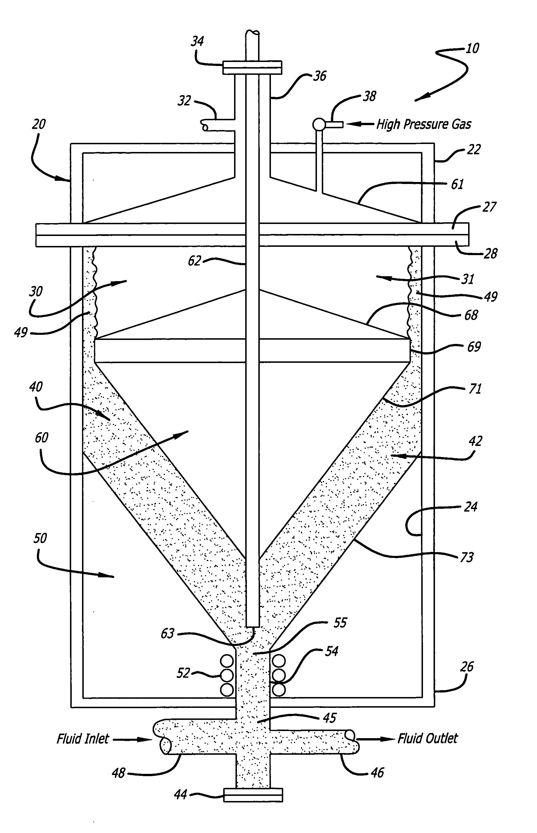
[0058] Container

[0059] Top: flat

[0060] Bottom: flat

[0061] Inside Diameter: 6.5 inches (16.5 cm)

[0062] Inside height: 14.5 inches (36.8 cm)

[0063] Flooded volume: 2.1 gallons (481 cubic inches, 7.9 liters)

[0064] Material: aluminum

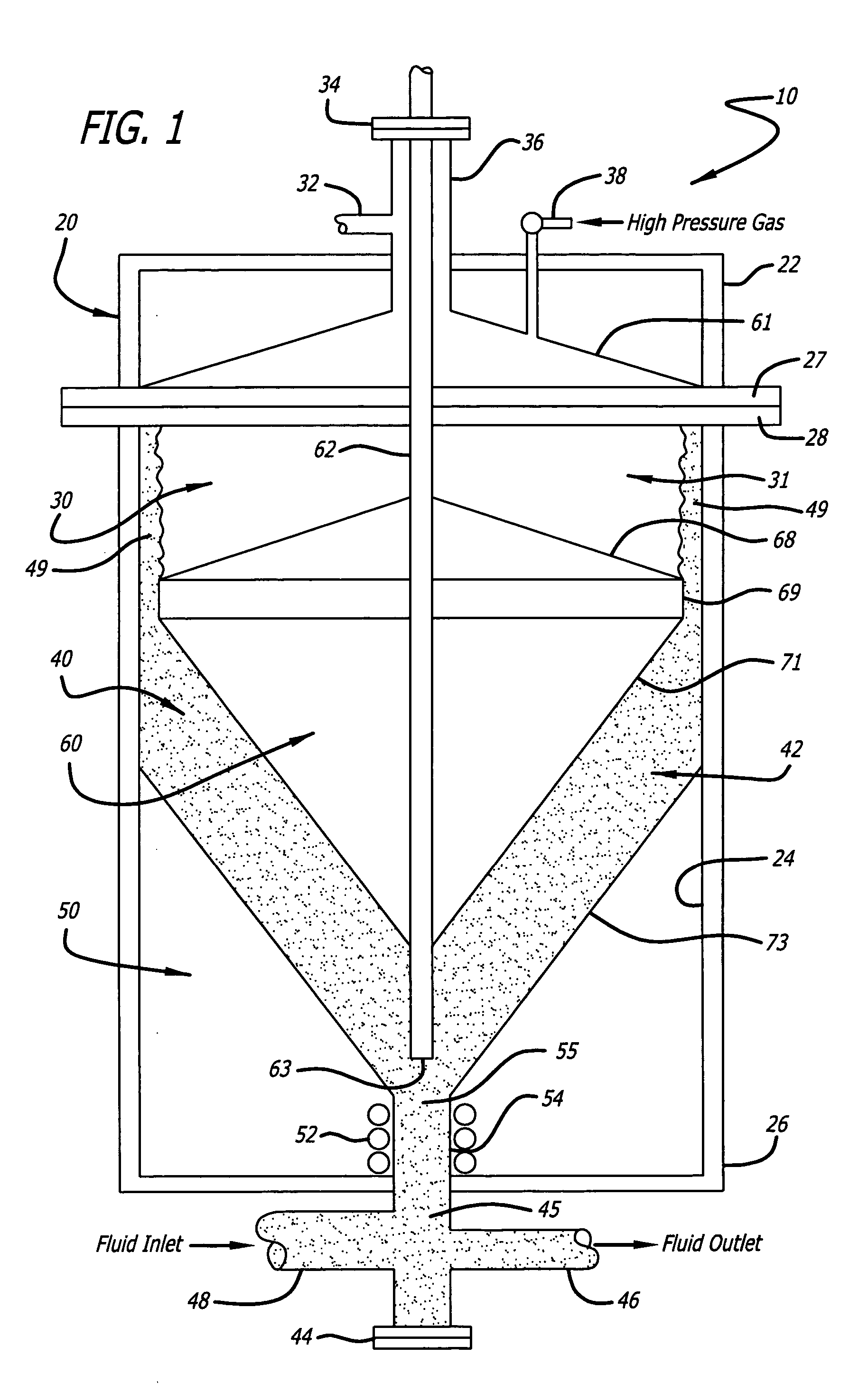
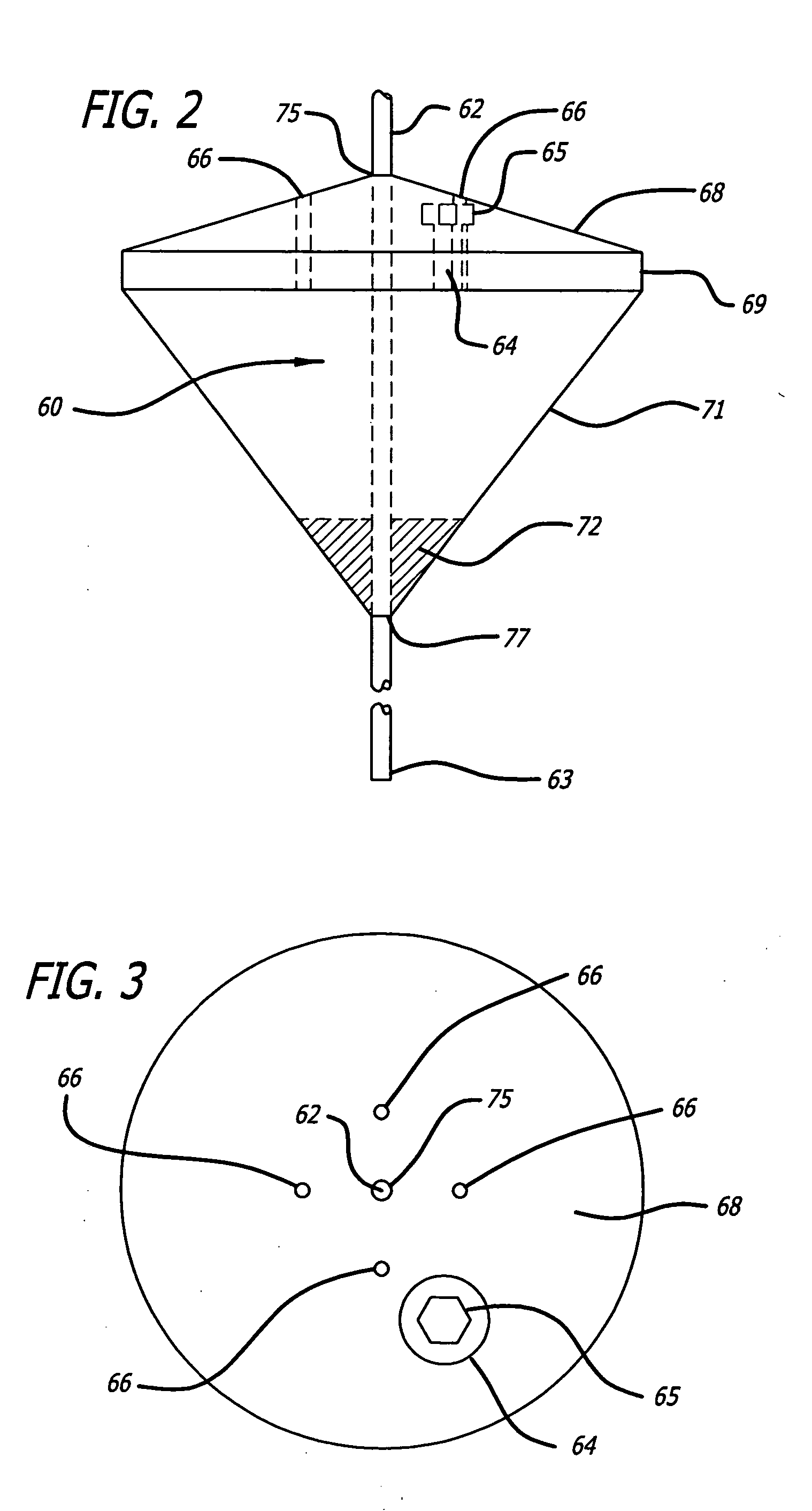
[0065] Force Transfer Device

[0066] Top: flat

[0067] Bottom: 120 degree cone

[0068] Bottom protuberance: none

[0069] Tangential diameter: 6.25 inches (15.9 cm)

[0070] Tangential height: 1.0 inches (2.5 cm)

[0071] Material: aluminum

example no.2

EXAMPLE NO. 2

Automotive Body Sound Deadening Dispenser

Dispensing Volume: 21.7 Gallons (5,013 Cubic Inches, 82.1 Liters)

[0072] Container

[0073] Top: 2:1 semi-ellipsoidal

[0074] Bottom: 2:1 semi-ellipsoidal

[0075] Inside Diameter: 15.5 inches (39.4 cm)

[0076] Straight shell height: 32.1 inches (81.5 cm)

[0077] Flooded volume: 34.3 gallons (7,929 cubic inches, 129.9 liters)

[0078] Material: stainless steel

[0079] Force Transfer Device

[0080] Top: 2:1 semi-ellipsoidal

[0081] Bottom: 2:1 semi-ellipsoidal

[0082] Bottom protuberance: diameter of 3.0 inches (7.6 cm) and height of 2.5 inches (6.4 cm)

[0083] Tangential diameter: 14.0 inches (35.6 cm)

[0084] Tangential height: 5.0 inches (12.7 cm)

[0085] Material: stainless steel

[0086] Proximity of the tangential member 69, 95, 230, 232, 234, 236, 330, 332, 334, 346, 348 of the force transfer device 60, 90, 200 and 300 to the sidewall 24 of the material container 20, 120 is dependant, among other things, upon the nature of the material 42. ...


PUM


Abstract

A material transfer system for storing, transferring and dispensing viscous material, such as fluids and liquids, includes a material containment vessel with an upper region incorporating a motive force and a bottom region with a material ingress and egress opening. A diconical or other shaped force transfer device is located in the material containment area. The force transfer device is an energy transducer when the material containment is filled with highly viscous materials, such as adhesives, sealants, mastics or lubricating greases. The force transfer device serves as an integral part of a level indicator for both viscous fluids and lower viscosity liquids. The viscous material itself forms a seal between the interface region of the force transfer device and the inside wall of the fluid vessel. Vertical stabilizing elements may extend outward from the force transfer device.

Description

CROSS-REFERENCE TO RELATED APPLICATION [0001] This application claims the benefit of U.S. Provisional Application Ser. No. 60 / 558,691, filed Mar. 31, 2004, the content of which is hereby incorporated herein by reference.BACKGROUND OF THE INVENTION [0002] The present invention relates to the field of materials management, and more particularly to systems designed for containing, transferring, delivering and dispensing various materials. The material management system of the invention is configured to deliver contamination free streams from a vessel that can be emptied and refilled repeatedly, without intervening cleaning of the vessel or its components. [0003] Prior known material management systems have encountered difficulty transferring from a containment vessel certain thick, viscous fluids, liquids and other types of materials that may resist pumping and that can be damaging to pumping apparatus. As used herein, a fluid is a substance that is capable of flowing and that changes ...

Claims


Application Information

Patent Timeline
Patent Type & Authority Applications(United States)
IPC IPC(8): B67D7/02A21C1/00
CPCB67D7/0238B67D7/0227
Inventor THIBODEAU, ROBERT D.WILLIAMS, ERIC A.
Owner CH & I TECH INC
Why Eureka
Try Eureka