
Multi-layer duct and related manufacturing process

a manufacturing process and multi-layer technology, applied in the field of multi-layer ducts, can solve the problems of superfluous application of additional layers of fluid tightening resin, remarkably complicated process, and high cost of duct cleaning, so as to reduce the internal roughness of the duct, the effect of easy removal of the mandrel

Inactive Publication Date: 2005-10-20
SALVER
View PDF4 Cites 12 Cited by
  • Summary
  • Abstract
  • Description
  • Claims
  • Application Information

AI Technical Summary

Benefits of technology

[0014] Besides these requisites, further operating conditions should be satisfied, such as the structural consistency of the multi-layer duct, the low noise associated to the flow of fluid and the optional electrical conductivity along the duct, to prevent the accumulation of electrostatic charges generated by friction of the fluid (air) against the inner walls of the duct.
[0023] The main advantage of the multi-layer duct as defined above lies in exhibiting reduced thicknesses, and therefore a limited weight per unit surface area (areal weight), satisfying the requisites of air-tightness. Concomitantly, the application of additional layers of fluid-tightening resin becomes superfluous.
[0025] According to a preferred embodiment of said process, the deposition of said polymer film on the mandrel is preceded by the applying on the mandrel of a detaching agent, e.g. a polyvinyl alcohol (PVA) resin or a polyester applied by spraying, which makes it easier to remove the mandrel, yet contributes to the decrease of the internal roughness of the duct, in particular in the case in which the mandrel is of a disposable, non-metallic type.

Problems solved by technology

However, the use of such materials requires great care with regard to the fluid- (air-) tightness of the duct.
This application remarkably complicates the process, as it is not possible to apply the required resin thickness in a single step.
Concomitantly, the application of additional layers of fluid-tightening resin becomes superfluous.

Method used


Image

  • Multi-layer duct and related manufacturing process
  • Multi-layer duct and related manufacturing process

Examples


Embodiment Construction

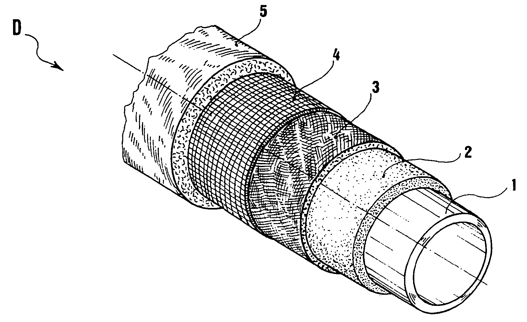
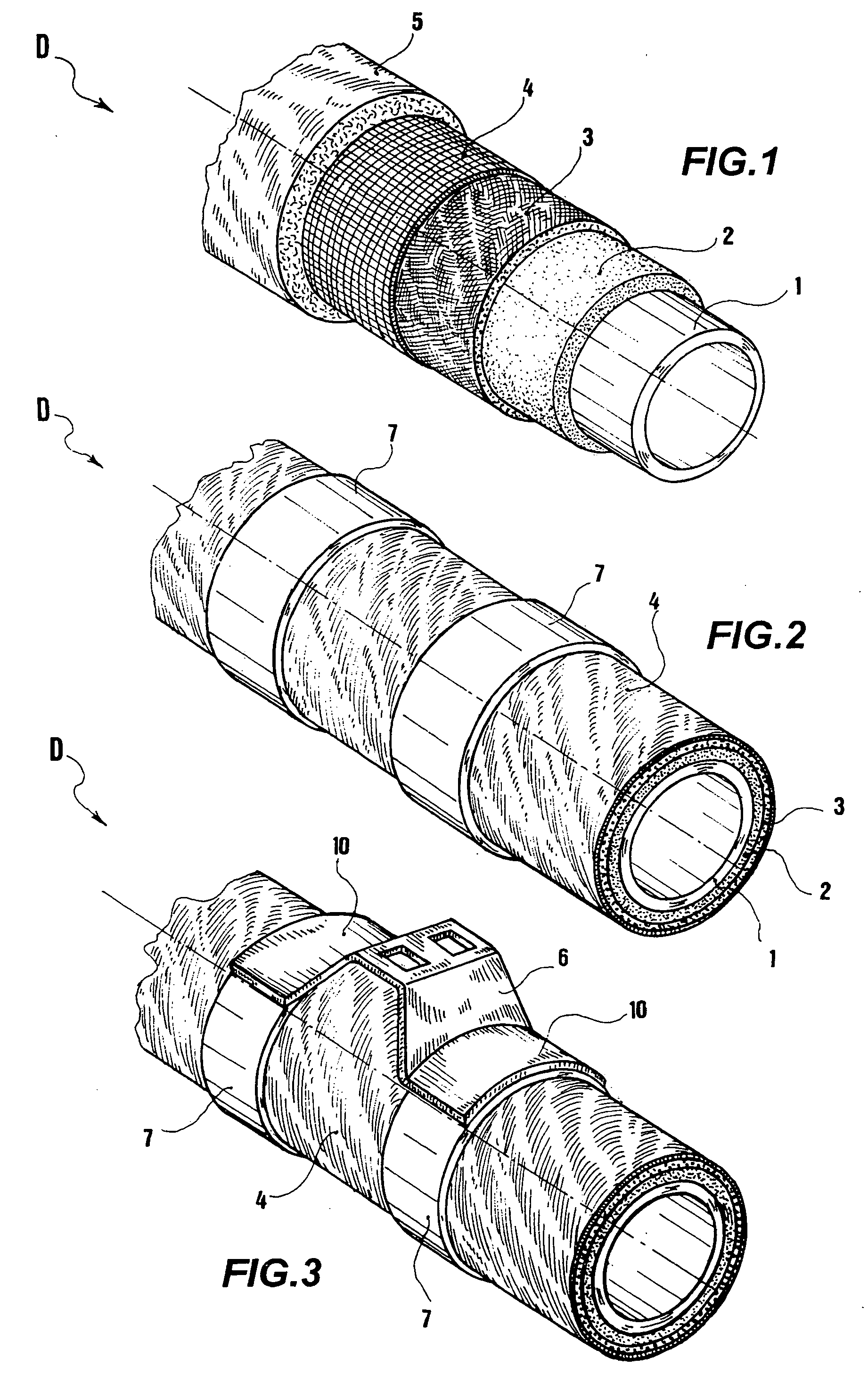
[0030] With reference to the figures, a multi-layer duct, in particular for aeronautical applications, is indicated by D and it is depicted in order to display the layers making it up.

[0031] These layers are coaxially arranged and will be described from the inside of the duct, where the passage of airflow is envisaged, to the outside of the duct. The shape of the depicted duct section is substantially circular, yet it is proposed that the shape of the duct and of its cross section may be any one.

[0032] The duct D comprises a substantially fluid tight polymer film 1, defining the inner wall of the duct. Advantageously, yet not exclusively, it is made of a flexible polymer material that may be wound around a mandrel in the first duct manufacturing step.

[0033] The polymer material may be a polyvinyl fluoride (PVF), a polytetrafluoride (PTF, PTFE), a phenolic or polyphenolic, polysulphonic and polyimidic material. Preferably, such a material is selected from a group comprising polyvi...


PUM

PropertyMeasurementUnit
Timeaaaaaaaaaa
Thicknessaaaaaaaaaa
Weightaaaaaaaaaa

Abstract

A multi-layer duct for air distribution in air conditioning systems, in particular, yet not exclusively, for aircraft vehicles, is made through a process providing an overlapping of layers of advanced composite materials, comprising: one substantially fluid tight polymer film, defining the inner wall of the duct; at least one stiffening structural layer, formed by a sheet of structural fibres preimpregnated in a polymer matrix of thermosetting resin, enveloping said polymer film; and one or more optional additional functional layers of structural and / or functional fibres, preimpregnated in a polymer matrix of thermosetting resin.

Description

RELATED APPLICATIONS [0001] This application claims priority to European Application Serial No. EP04425275.7, filed Apr. 20, 2004, entitled “MULTI-LAYER DUCT AND RELATED MANUFACTURING PROCESS,” and which is incorporated herein by reference. BACKGROUND OF THE INVENTION [0002] 1. Field of the Invention [0003] The present invention refers to a multi-layer duct for air distribution in air conditioning systems, in particular, yet not exclusively, for aircraft vehicles. The invention further refers to a process for manufacturing such a duct. [0004] 2. Description of the Prior Art [0005] The duct manufacturing technology that uses the overlapping of layers of material to make up the walls of the duct has witnessed the taking hold of the advanced composite materials, in the form of the so-called prepreg, provided in rolls and / or sheets of the desired thickness. [0006] For ‘prepreg’ (preimpregnated composite material) it is meant hereinafter a fabric, unidirectional tape, mats, strands, non-...

Claims


Application Information

Patent Timeline
IPC IPC(8): B29C70/06B29C70/08B29C70/16B29C70/32B29K105/08B32B1/08B32B5/28B32B27/12F16L9/12F16L11/127F24F13/02
CPCB29C70/086B29C70/32F16L11/127B32B27/12F16L9/125B29L2023/22Y10T428/24994Y10T428/249924B32B7/12B32B2597/00B32B27/42B32B1/08B32B2260/021B32B2262/106B32B2262/101B32B2262/0269B32B2260/046B32B27/322B32B2262/04B32B27/281B32B27/286
Inventor CAPOCCELLO, DANIELEINNOCENTE, FRANCESCO
Owner SALVER
Learn More