Power supply system, fuel pack constituting the system, and device driven by power generator and power supply system

a technology of power supply system and fuel pack, which is applied in the direction of portable application adaption, electrically conductive generator, sustainable building, etc., can solve the problems of battery capacity not being recovered, environmental destruction and disfigurement of the natural environment, etc., and achieve the effect of suppressing waste of power generation fuel and effective use of energy resources

Inactive Publication Date: 2005-10-20
CASIO COMPUTER CO LTD
View PDF6 Cites 33 Cited by
  • Summary
  • Abstract
  • Description
  • Claims
  • Application Information

AI Technical Summary

Benefits of technology

[0016] In view of the above-described problems, the present invention has an advantage of providing a power generation module, a fuel pack and a power supply system including these members which can stably and excellently actuate a device using a general-purpose chemical cell as operating electric power and achieve effective use of an energy resource by suppressing waste of a power generation fuel.

Problems solved by technology

In recent years, with the rising interest in environmental concerns or energy problems, problems concerning waste materials generated after use of chemical cells such as described above or those concerning the energy conversion efficiency have come under close scrutiny.
Further, basically, when the primary cell is once discharged, the battery capacity can not be recovered, namely, it can be used only once (which is a so-called disposable battery).
Thus, there is fear of environmental destruction and disfigurement of the natural environment by heavy metal such as mercury or indium included in such uncollected batteries.
Moreover, a fuel cell portion in the power supply system is also a durable material and, in particular, a catalyst provided inside the fuel cell is apt to be deteriorated by use of a heater or the like.
In addition, it is impossible to avoid a problem that constituent parts (for example, a fuel tank and others) of the power supply system after the power generation fuel has been used up or its durable period has passed are discarded as waste materials, and there is the possibility that the problem of environmental destruction or disfigurement of natural environment may occur as similar to the above-described chemical cell.
Usually, although the fuel battery generates power by bringing alcohol fuel or hydrogen gas including a hydrogen element into contact with one of electrodes, the fuel cell itself does not control start and stop of power generation.
In the power supply system including the fuel cell utilized as a power supply for a portable device in particular, therefore, even if the device is in the off mode or the standby mode and requires less power, the electric power to be supplied to the device is constantly outputted as similar to a general chemical cell and power is hence always generated, thereby deteriorating the consumption efficiency of the fuel.

Method used


Image

  • Power supply system, fuel pack constituting the system, and device driven by power generator and power supply system
  • Power supply system, fuel pack constituting the system, and device driven by power generator and power supply system
  • Power supply system, fuel pack constituting the system, and device driven by power generator and power supply system

Examples


first embodiment

[0134] (A) Power Generation Module 10

[0135]FIG. 3 is a block diagram showing a first embodiment of a power generation module applied to the power supply system according to the present invention, and FIG. 4 is a schematic view showing a structure of the power supply system according to this embodiment.

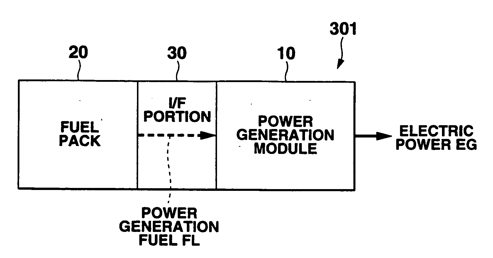
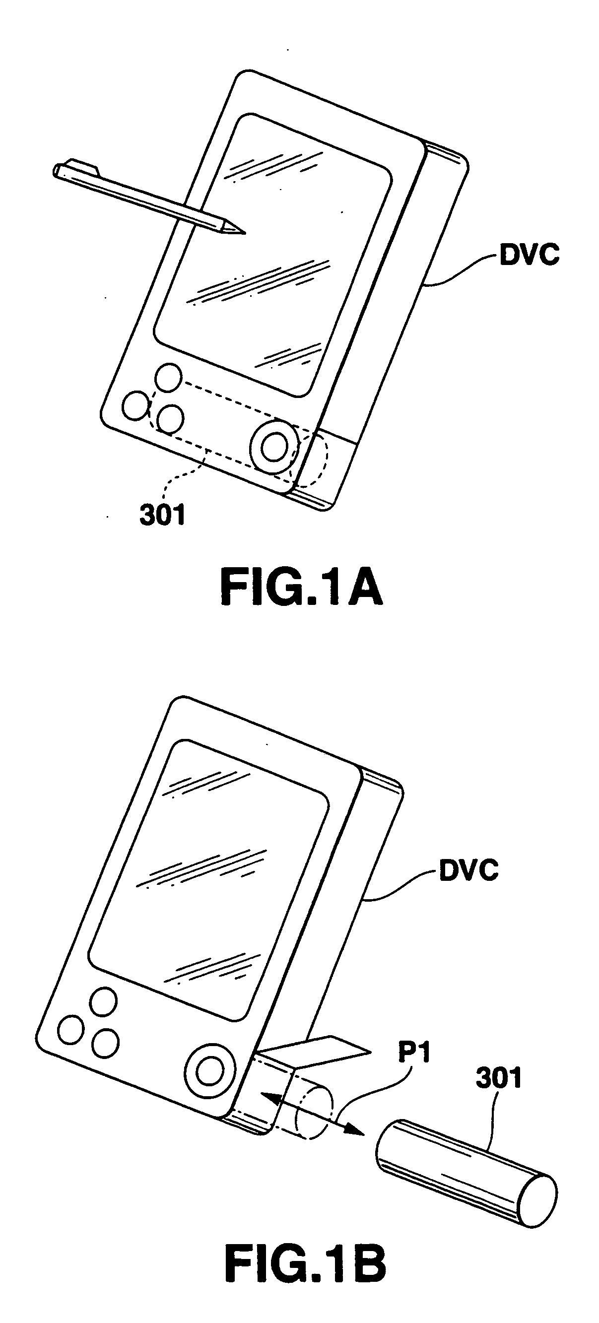
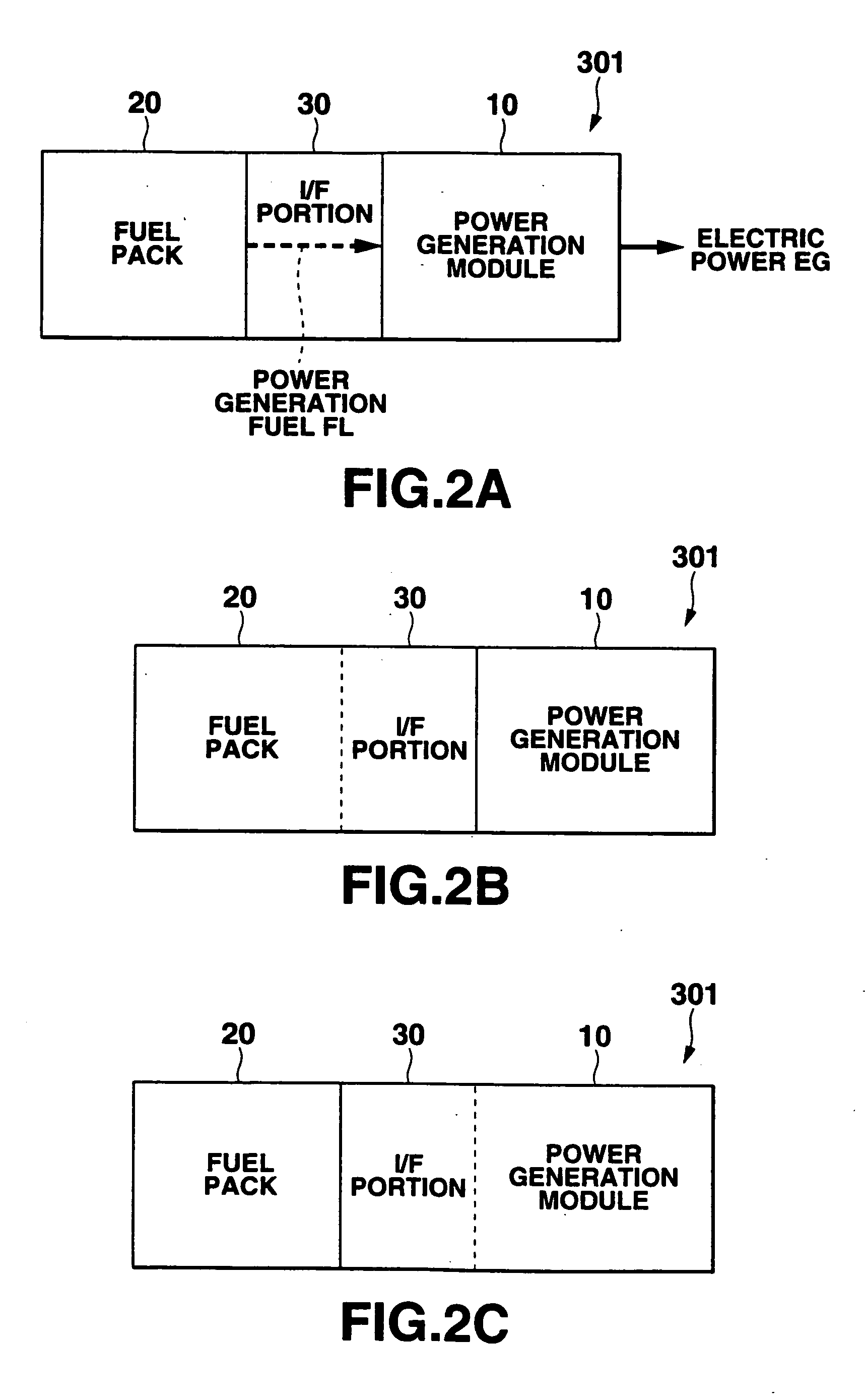
[0136] As shown in FIG. 3, a power generation module 10A according to this embodiment constantly autonomously generates predetermined electric power (second electric power) by using a power generation fuel supplied from a fuel pack 20A through an I / F portion 30A and outputs it as a drive electric power (controller electric power) for a controller CNT which is included in the device DVC connected to at least the power supply system 301 and controls to drive a load LD (an element or a module having various kinds of functions of the device DVC). There is provided a sub power supply portion (second power supply means) 11 for outputting power as operating power for a later-described operat...

second embodiment

[0351] A second embodiment of the power generation module applied to the power supply system according to the present invention will now be described with reference to the drawings.

[0352]FIG. 32 is a block diagram showing a second embodiment of the power generation module applied to the power supply system according to the present invention, and FIG. 33 is a view schematically showing the electrical connection relationship between the power supply system (power generation module) according to this embodiment and the device. Here, like reference numerals denote structures similar to those in the above-described first embodiment, thereby simplifying or omitting their explanation.

[0353] As shown in FIG. 32, the power generation module 10B according to this embodiment generally includes: a sub power supply portion (second power supply means) 11 having functions similar to those in the above-described first embodiment (see FIG. 3); a power generation portion (first power supply means) ...

third embodiment

[0376] A third embodiment of the power generation module applied to the power supply system according to the present invention will now be described with reference to the drawings.

[0377]FIG. 43 is a block diagram showing a third embodiment of the power generation module applied to the power supply system according to the present invention. Here, as similar to the second embodiment mentioned above, although description will be given as to the structure in which predetermined information is notified between the power supply system and the device to which the power supply system is connected through the terminal portion ELx, it is needless to say that there may be provided a structure in which the power supply system is connected with the device only through the electrode terminals (the positive electrode terminal and the negative electrode terminal) and any special notification is not carried out between the power supply system and the device as similar to the first embodiment. Furth...


PUM

PropertyMeasurementUnit
temperatureaaaaaaaaaa
widthaaaaaaaaaa

Abstract

A fuel pack with a space for storing a fuel is provided which includes a case, wherein the case includes a feed port for exhausting the fuel to outside of the fuel pack, and at least a portion of the case is formed of a biodegradable material.

Description

CROSS-REFERENCE TO RELATED APPLICATIONS [0001] The present application is a Divisional application of U.S. application Ser. No. 10 / 023,269, filed on Dec. 18, 2001, which is based upon and claims the benefit of priority from the prior Japanese Patent Applications No. 2000-388398, filed Dec. 21, 2000; No. 2001-009373, filed Jan. 17, 2001; and No. 2001-280356, filed Sep. 14, 2001, the entire contents of all of which are incorporated herein by reference.BACKGROUND OF THE INVENTION [0002] 1. Field of the Invention [0003] The present invention relates to a power supply system, and more particularly to a portable power supply system capable of effectively utilizing an energy resource, a fuel pack constituting the power supply system, and a device driven by a power generator and the power supply system. [0004] 2. Description of the Related Art [0005] In all household and industrial fields, various kinds of chemical cells are used. For example, a primary cell such as an alkaline dry cell or ...

Claims


Application Information

Patent Timeline
Patent Type & Authority Applications(United States)
IPC IPC(8): H01M8/04H01M8/06
CPCH01M8/04Y02B90/18H01M8/04208H01M8/04373H01M8/04425H01M8/04559H01M8/04567H01M8/04626H01M8/04679H01M8/04686H01M8/04753H01M8/04776H01M8/0612H01M16/003H01M2250/30Y02E60/50H01M8/04007Y02B90/10
Inventor SHIOYA, MASAHARU
Owner CASIO COMPUTER CO LTD
Why Eureka
Try Eureka