Method for fabricating envelope and method for fabricating image display apparatus

a technology of image display apparatus and envelope, which is applied in the direction of image/pattern display tubes, tubes with screens, basic electric elements, etc., can solve the problems of reducing the time required for temperature regulation, affecting the display quality, etc., and achieves satisfactory display quality.

Inactive Publication Date: 2005-10-20
CANON KK
View PDF24 Cites 3 Cited by
  • Summary
  • Abstract
  • Description
  • Claims
  • Application Information

AI Technical Summary

Benefits of technology

[0010] An objective of the present invention is to provide a method for fabricating an envelope, which has a high freedom in process, is economical and allows an easy process management.
[0016] The fabricating method of the present invention, employing the aforementioned specific steps in the fabrication of the envelope, can attain the aforementioned objective of the invention and can economically provide an image display device and an image display apparatus of a satisfactory display quality.

Problems solved by technology

However, the vacuum baking step and the sealing step executed in a same chamber result in a drawback of an elongated process time required for temperature regulation and the like.
However, such prior process is associated with following drawbacks.
Firstly, the In coating step cannot be executed effectively in vacuum because of In scattering, and has to be executed prior to the baking step because the steps of baking and thereafter are all executed in vacuum in the prior technology, so that the process lacks freedom.
Also the spacer provided on the rear plate is heated to a high temperature by vacuum baking, and a rapid temperature change induces a bending of the rear plate and a cracking of the spacer.
Thus, there are required measures against the cracking of the spacer, such as a temperature control by upper and lower heaters at the carrying operation, involving a difficulty in the temperature control and an increased cost of the apparatus.
On the other hand, a carrying in an inert gas atmosphere also requires measures for preventing oxygen deficiency or choking around the carrying facility, resulting in a difficult process control and an increase in the facility cost.

Method used


Image

  • Method for fabricating envelope and method for fabricating image display apparatus
  • Method for fabricating envelope and method for fabricating image display apparatus
  • Method for fabricating envelope and method for fabricating image display apparatus

Examples


Embodiment Construction

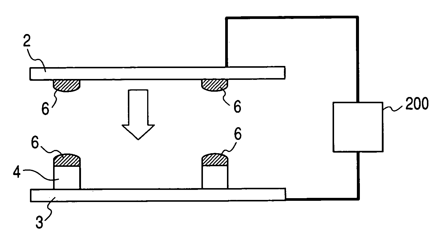
[0034] The present invention has been made in consideration of the aforementioned drawbacks, and provides a method for fabricating an envelope formed by sealing a first member and a second member and containing a vacuum space therein. The fabricating method for the envelope of the present invention includes a step of baking the first member and the second member in vacuum in a first chamber, a carrying step of carrying the first member and the second member thus baked from the first chamber to a second chamber in an atmosphere in which an air having a predetermined dew point is maintained at a temperature exceeding such dew point, and a sealing step of sealing the first member and the second member in vacuum in the second chamber thereby forming the envelope. In the baking step, the first member and the second member may be baked simultaneously or separately. Also in the carrying step, the first member and the second member may be carried simultaneously or separately.

[0035] In such...


PUM


Abstract

The present invention provides a method for fabricating an envelope, which has a high freedom of process, is economical and allows an easy process management. The method aims to fabricate an envelope formed by sealing first and members, the envelope having a vacuum space therein, and basically comprises a step of baking the first and second members in vacuum in a first chamber, a carrying step of carrying the first and second members subjected to baking from the first chamber to a second chamber in an atmosphere in which an air having a predetermined dew point is maintained at a temperature exceeding such dew point, and a sealing step of sealing the first and second members in vacuum in the second chamber thereby forming the envelope. The method allows to economically provide an image display device and an image display apparatus of satisfactory display quality.

Description

BACKGROUND OF THE INVENTION [0001] 1. Field of the Invention [0002] The present invention relates to a method for fabricating an envelope for maintaining a vacuum interior, and a method for fabricating an image display apparatus utilizing the method for fabricating the envelope. [0003] 2. Related Background Art [0004] An electron emitting device has been known in two types of a hot electron source and a cold cathode electron source. The cold cathode electron source includes an electric field emission device (FE device), a metal / insulator / metal device (MIM device), a surface conduction electron emitting device (SCE device) etc. [0005]FIG. 12 schematically shows an envelope 91 utilizing an electron source substrate, in which such electron emitting devices (an surface conduction electron emitting device being shown as an example) are arranged in a matrix shape. A rear plate 93 is a glass substrate provided, on one side thereof, with an electron source substrate 131 on which a plurality...

Claims


Application Information

Patent Timeline
Patent Type & Authority Applications(United States)
IPC IPC(8): H01J9/24H01J9/26H01J31/12
CPCH01J9/261
Inventor HASEGAWA, MITSUTOSHI
Owner CANON KK
Why Eureka
Try Eureka