Automotive movable body, movable body control method and computer program

a technology of movable bodies and control methods, applied in the direction of process and machine control, distance measurement, instruments, etc., can solve the problems of cleaning the entire area, cleaning cannot go away from obstacles, and cannot clean the entire area, so as to achieve high precision, high precision, and high precision

Inactive Publication Date: 2005-10-20
SANYO ELECTRIC CO LTD
View PDF4 Cites 17 Cited by
  • Summary
  • Abstract
  • Description
  • Claims
  • Application Information

AI Technical Summary

Benefits of technology

[0033] Moreover, with the present invention, even when it is difficult to moving straight toward the wall detected first by a sensor due to the state of the floor surface, such as floor surface roughness, the body can move toward the wall while correcting the moving direction according to detection results of the plurality of sensors, so that the movable body can move while judging the position of the movable body accurately without using position measuring means which is expensive and of high precision.
[0034] Moreover, with the present invention, even when it is difficult to move straight toward the wall after going away from the wall and turning around due to the state of the floor surface, such as floor surface roughness, the body can move toward the wall after correcting the moving direction according to detection results of the plurality of sensors after going away from the wall next and turning around, so that the body can move after correcting the moving direction of the movable body to

Problems solved by technology

H7-319542 has a problem that it can move only in one side area of an obstacle and cannot move to the other side area when an obstacle exists between the opposing walls, or it cannot get out of a dead end only by the zigzag moving control and cannot clean the entire area when a dead end is formed due to the shape of the wall.
H9-179625 has a problem that, when a substantially cylindrical obstacle exists between the opposing walls when a substantially cylindrical obstacle exists between the opposing walls, the cleaner moves away from the obstacle in the normal direction of a substantially cylindrical obstacle which the cleaner has come into contact with or close to and then moves again to the obstacle in a direction having a pred

Method used


Image

  • Automotive movable body, movable body control method and computer program
  • Automotive movable body, movable body control method and computer program
  • Automotive movable body, movable body control method and computer program

Examples


embodiment 1

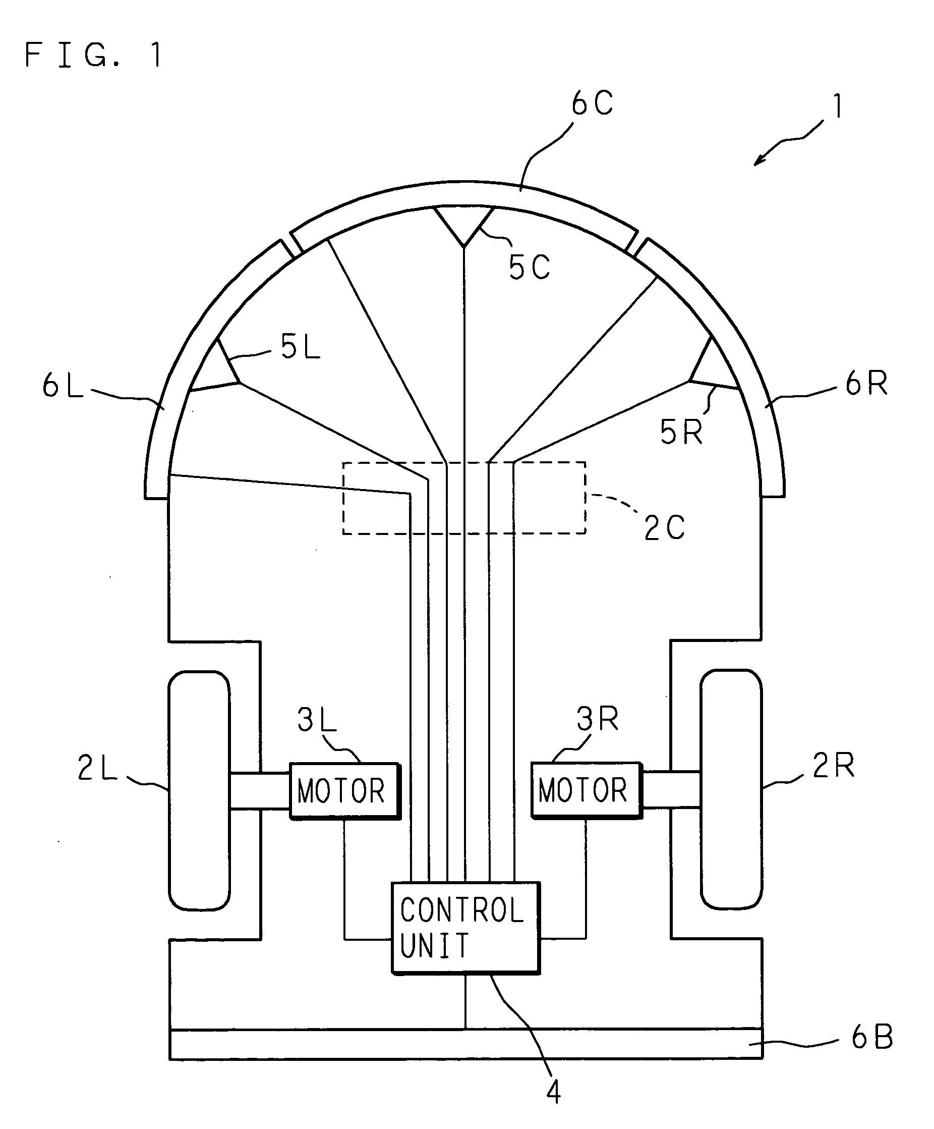
[0056]FIG. 1 is a block diagram showing an example of the schematic structure of an automotive movable body according to Embodiment 1 of the present invention. In FIG. 1, denoted at 1 is an automotive movable body, such as an automotive vacuum cleaner or an automotive lawn mower, which is used so as to move all over an area surrounded by a boundary such as a wall.

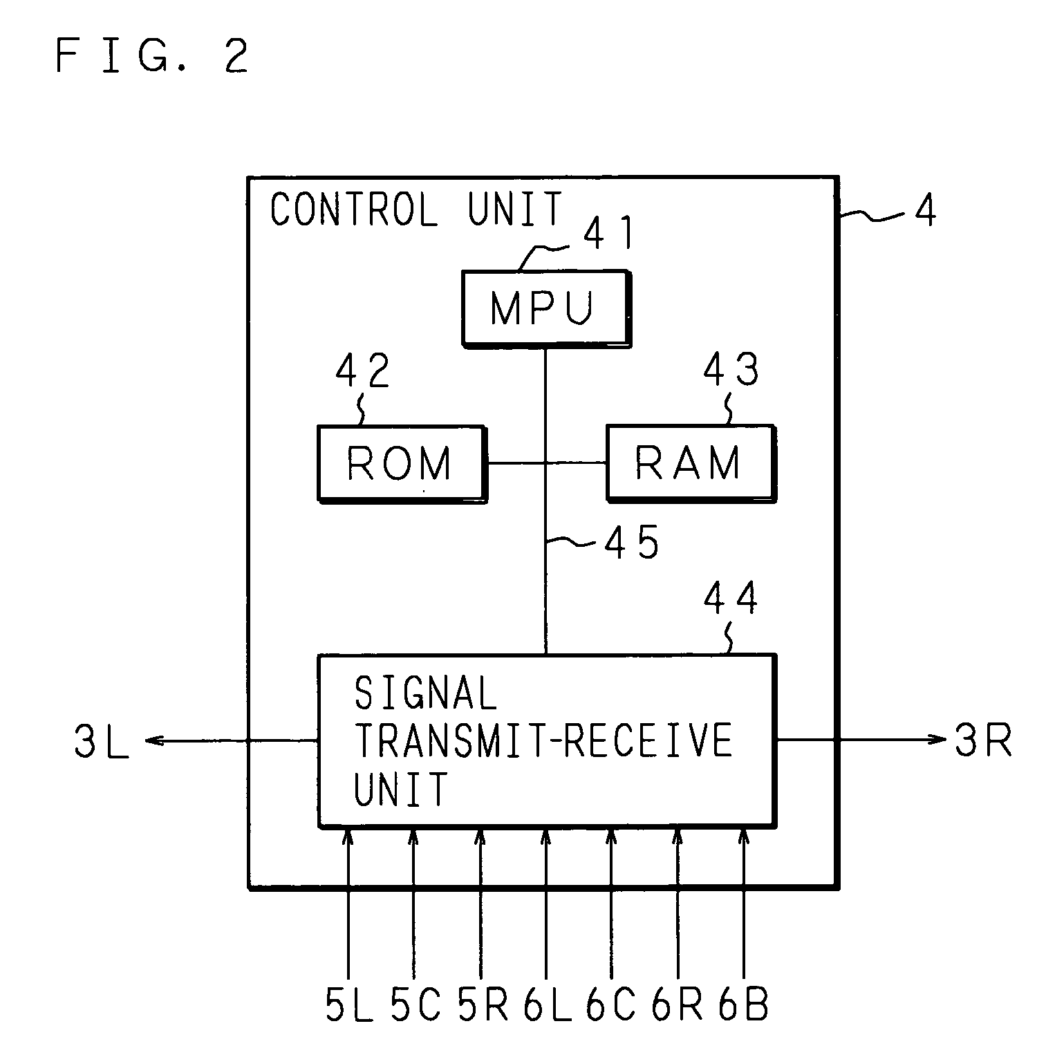
[0057] The automotive movable body 1 is composed of a pair of driven wheels 2L and 2R; a steering wheel 2C; motors 3L and 3R for driving the driven wheels 2L and 2R; a control unit 4 for controlling a drive of the motors; ultrasonic sensors 5L, 5C and 5R for detecting a wall, an obstacle or the like; and pressure sensors 6L, 6C, 6R and 6B for detecting a contact with a wall, an obstacle or the like.

[0058]FIG. 1 shows a state where the automotive movable body 1 is drawn in perspective from above a plane surface thereof and shows a left driven wheel 2L, a right driven wheel 2R and a steering wheel 2C. The axles of the left ...

embodiment 2

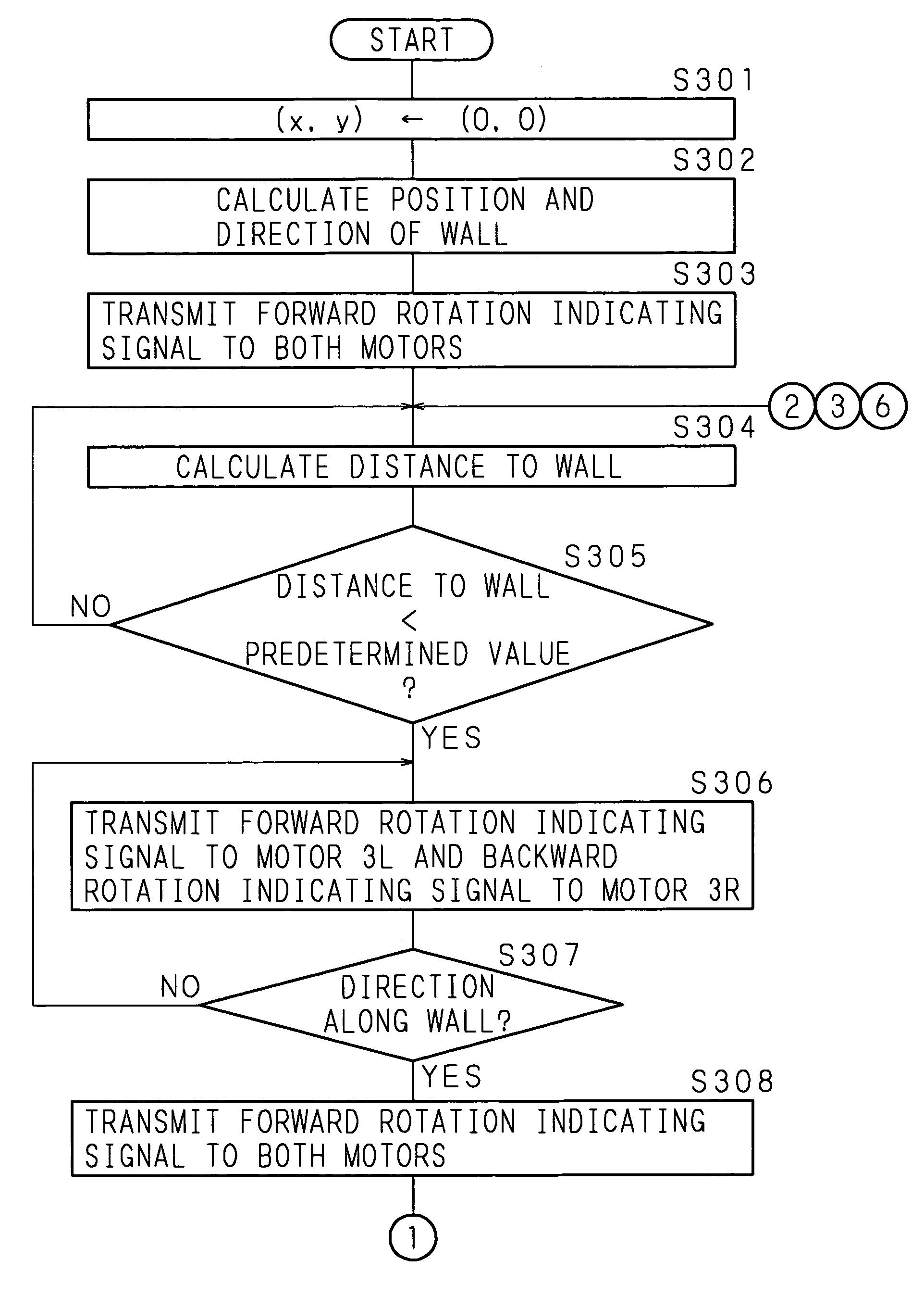
[0083] The following description will explain an automotive movable body 1 according to Embodiment 2 of the present invention. FIG. 8 is a flow chart showing a part of the operational control procedure of a control unit 4 of the automotive movable body 1 according to Embodiment 2 of the present invention. FIG. 8 illustrates a case where the body moves in a clockwise direction. It should be noted that the automotive movable body 1 according to Embodiment 2 of the present invention is the same as Embodiment 1 in construction and the detailed explanation thereof will be omitted by appending the same codes.

[0084] When the automotive movable body 1 is located in an area surrounded by a wall to start moving, the control unit 4 detects the position of the nearest surface of the wall on the basis of input signals from a plurality of sensors 5L, 5C and 5R. In particular, the MPU 41 resets the position coordinate counter (x, y) of the RAM 43 to (0, 0) when a moving start instruction is issue...

embodiment 3

[0096] Embodiment 3, which will explain an automotive movable body 1 according to Embodiment 3 of the present invention in the following description, is characterized in the moving control procedure to be performed after the automotive movable body 1 turns around at an approximately 180° and moves toward the wall. FIGS. 10, 11A and 11B are flow charts showing a part of the operational control procedure of a control unit 4 of the automotive movable body 1 according to Embodiment 3 of the present invention. FIGS. 10, 11A and 11B illustrate a case where the body moves in a clockwise direction. It should be noted that the automotive movable body 1 according to Embodiment 3 of the present invention is the same as Embodiment 1 in construction and the detailed explanation thereof will be omitted by appending the same codes.

[0097] The MPU 41 calculates the distance to a wall lying in front on the basis of signals inputted from ultrasonic sensors 5L, 5C and 5R (step S1001) and judges whethe...


PUM


Abstract

Provided are: an automotive movable body capable of moving to an entire area surrounded by a wall excluding an area where an obstacle exists no matter what shape an obstacle existing within the area has; a movable body control method; and a recording medium storing a computer program. An automotive movable body for which moving algorithm is specified moves toward an object detected at the time of start of moving and judges whether the distance to the object is shorter than a predetermined value or not. When it is judged that the distance is shorter than a predetermined value, the body moves a first distance along the object, then moves a second distance in a direction intersecting the segment connecting the position before moving with the position after moving, and then moves toward the position where moving of the second distance is started after turning around at approximately 180°.

Description

CROSS-REFERENCE TO RELATED APPLICATIONS [0001] This Nonprovisional application claims priority under 35 U.S.C. §119(a) on Patent Application No. 2004-124788 filed in Japan on Apr. 20, 2004, the entire contents of which are hereby incorporated by reference. BACKGROUND OF THE INVENTION [0002] The present invention relates to: an automotive movable body, such as an automotive vacuum cleaner or an automotive lawn mower, capable of moving within an area surrounded by a boundary such as a wall; a movable body control method; and computer program. [0003] With rapid advancement of robot control technology in recent years, some automotive movable bodies which can be utilized at home, such as an automotive vacuum cleaner and an automotive lawn mower, are being introduced into the market. Such an automotive movable body comprises a sensor for detecting a wall standing around, an obstacle existing within the area in which the body may move or the like, so that a predetermined operation can be p...

Claims


Application Information

Patent Timeline
IPC IPC(8): A47L9/28A47L9/00G05D1/00G05D1/02
CPCG05D1/0255G05D2201/0215G05D2201/0208
Inventor SHIMIZU, AKIOTOKUMARU, TOMOYOSHIHIROSE, TATSUYA
Owner SANYO ELECTRIC CO LTD
Why Eureka
Try Eureka