
Method and apparatus for clearance adjusting cover plate closure

a technology of cover plate closure and adjustment method, which is applied in the field of manufacturing and assembly of movable sockets, can solve the problems of erratic steering or excessive looseness deformation of movable sockets or ball joints employed in these applications, and play in the vehicle suspension system, so as to achieve precise control of the preload of the ball and socket components, the effect of high repeatability

Inactive Publication Date: 2005-10-27
FEDERAL MOGUL WORLD WIDE
View PDF11 Cites 21 Cited by
  • Summary
  • Abstract
  • Description
  • Claims
  • Application Information

AI Technical Summary

Benefits of technology

[0013] Briefly stated, the present invention provides a socket for a ball and socket joint which uses a socket housing which does not require a fully formed circumferential groove to capture the cover-plate in the housing opening. The housing incorporates a housing wall of deformable material, preferably a ductile material, to provide a closure system utilizing a deformable cover-plate to achieve a consistent preload of the internal ball and socket components. The cover-plate is deformed onto a step within the housing opening, beyond an elastic limit, whereby the deformed cover plate exhibits a high-degree of repeatability and precise control of the preload of the ball and socket components during the assembly process. The deformed cover-plate is retained in the socket housing at the cover-plate seat by swaging or spin forming the deformable perimeter of the housing proximate the top surface to capture the perimeter of the cover plate within the housing opening.
[0014] In one aspect, the invention is a method for assembling a socket which includes the steps of inserting the socket components into the housing through a housing opening, disposing a deformable cover-plate on a circumferential seat within the socket opening, exerting a controlled load on the deformable cover-plate to take the cover-plate beyond an elastic limit, thereby flattening and expanding the cover-plate to a desired configuration on the seat within the housing opening and providing a controlled preload and associated internal clearance of the ball and socket components, and capturing the perimeter edge of the cover-plate within the housing socket by swaging or spin forming a perimeter lip of the housing over the perimeter of the cover-plate, thereby retaining the socket components in the housing, and the cover-plate against the circumferential seat within the housing opening. Advantageously, the sequencing of the steps associated with deformation of the cover-plate and capturing the perimeter edge of the cover-plate by swaging or spin forming a perimeter lip may be reversed.
[0015] It is a further advantage of the method of the present invention that the housing may be formed with a straight counter bore and does not require the formation of a separate circumferential groove as has been utilized with prior methods of forming sockets.

Problems solved by technology

Obviously, movable sockets or ball-joints employed in these applications are subjected to various operating conditions, and may be required to carry substantial loads.
When wear develops, the performance of the movable socket or ball-joint degrades and, in the case of automotive applications, may result in erratic steering or excessive looseness and play in the vehicle suspension system.
However, some socket designs require a sealed or closed cover-plate having no axial opening.

Method used


Image

  • Method and apparatus for clearance adjusting cover plate closure
  • Method and apparatus for clearance adjusting cover plate closure
  • Method and apparatus for clearance adjusting cover plate closure

Examples


first embodiment

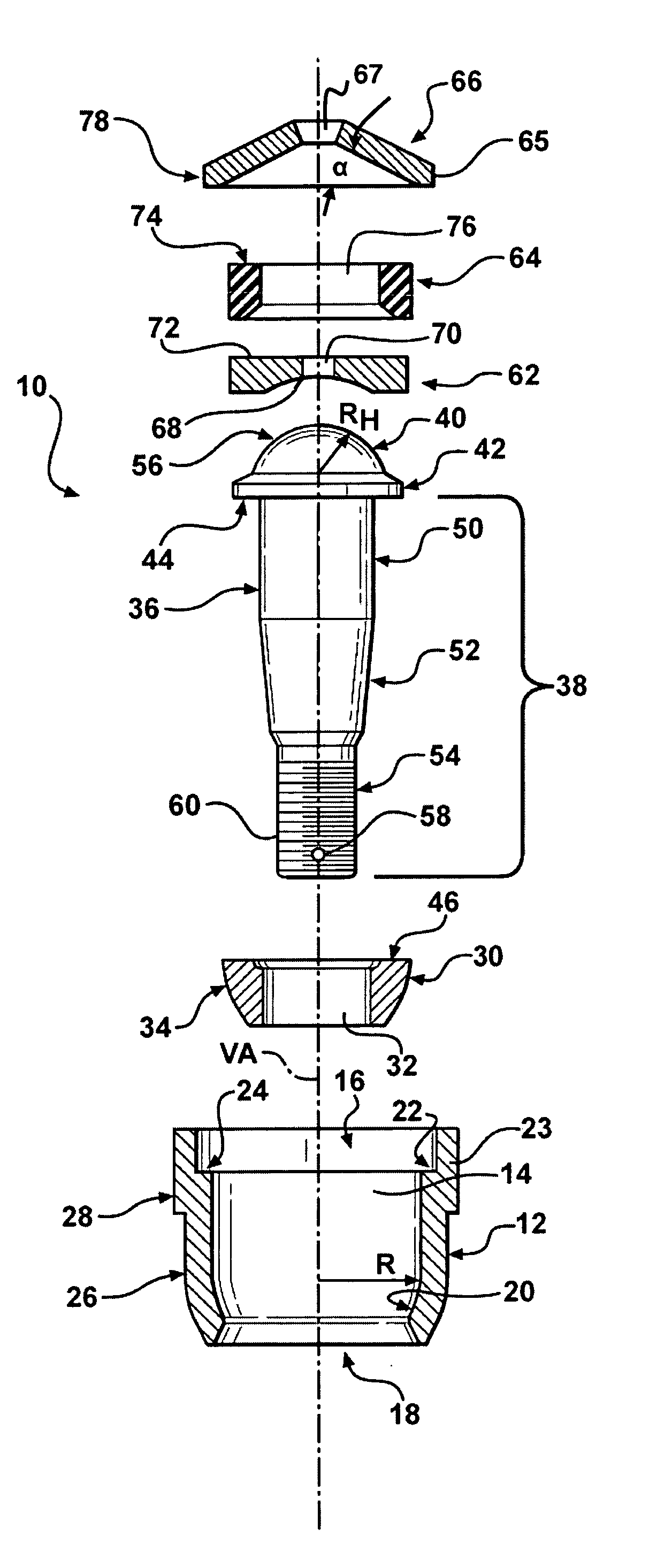
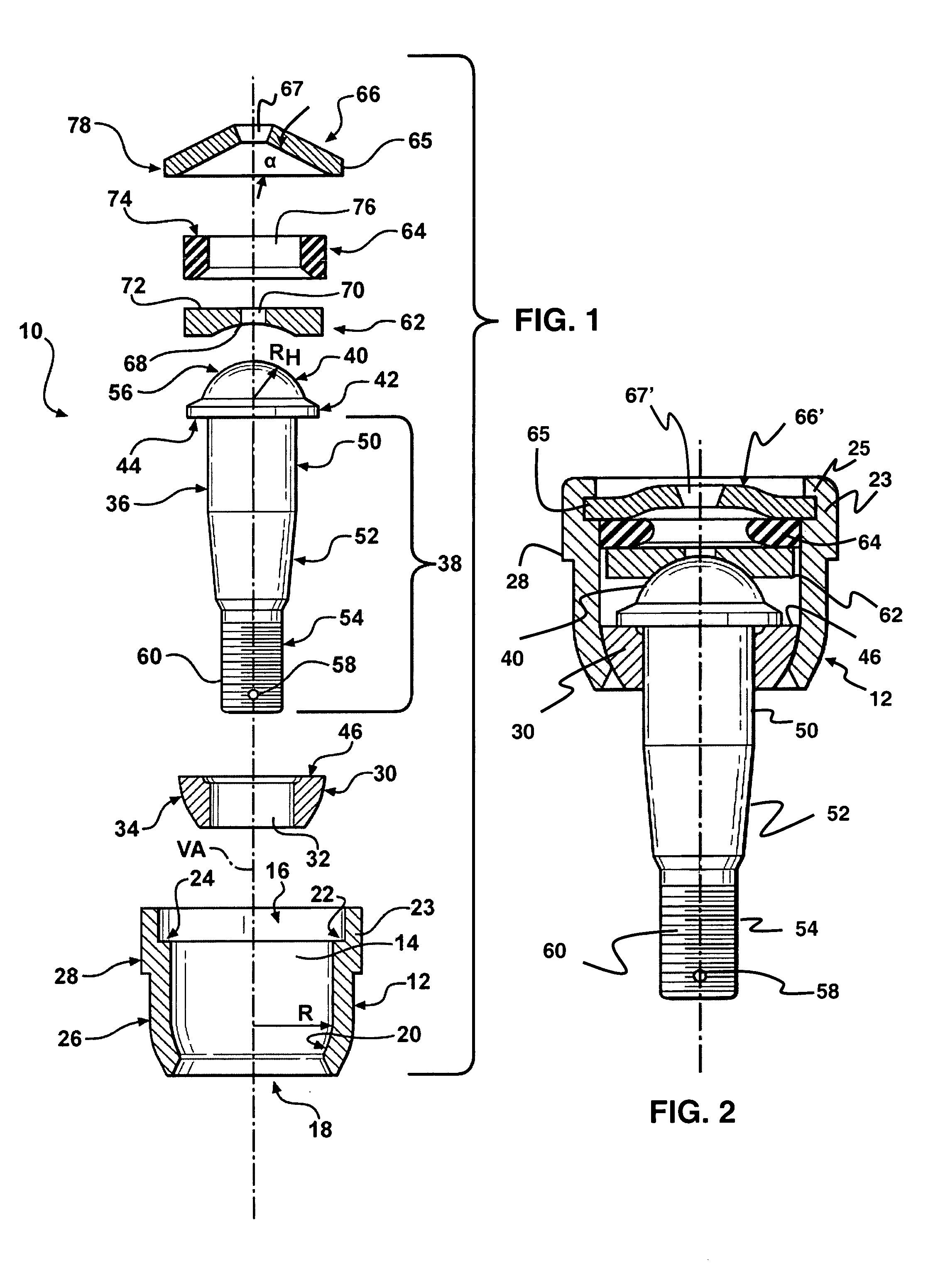
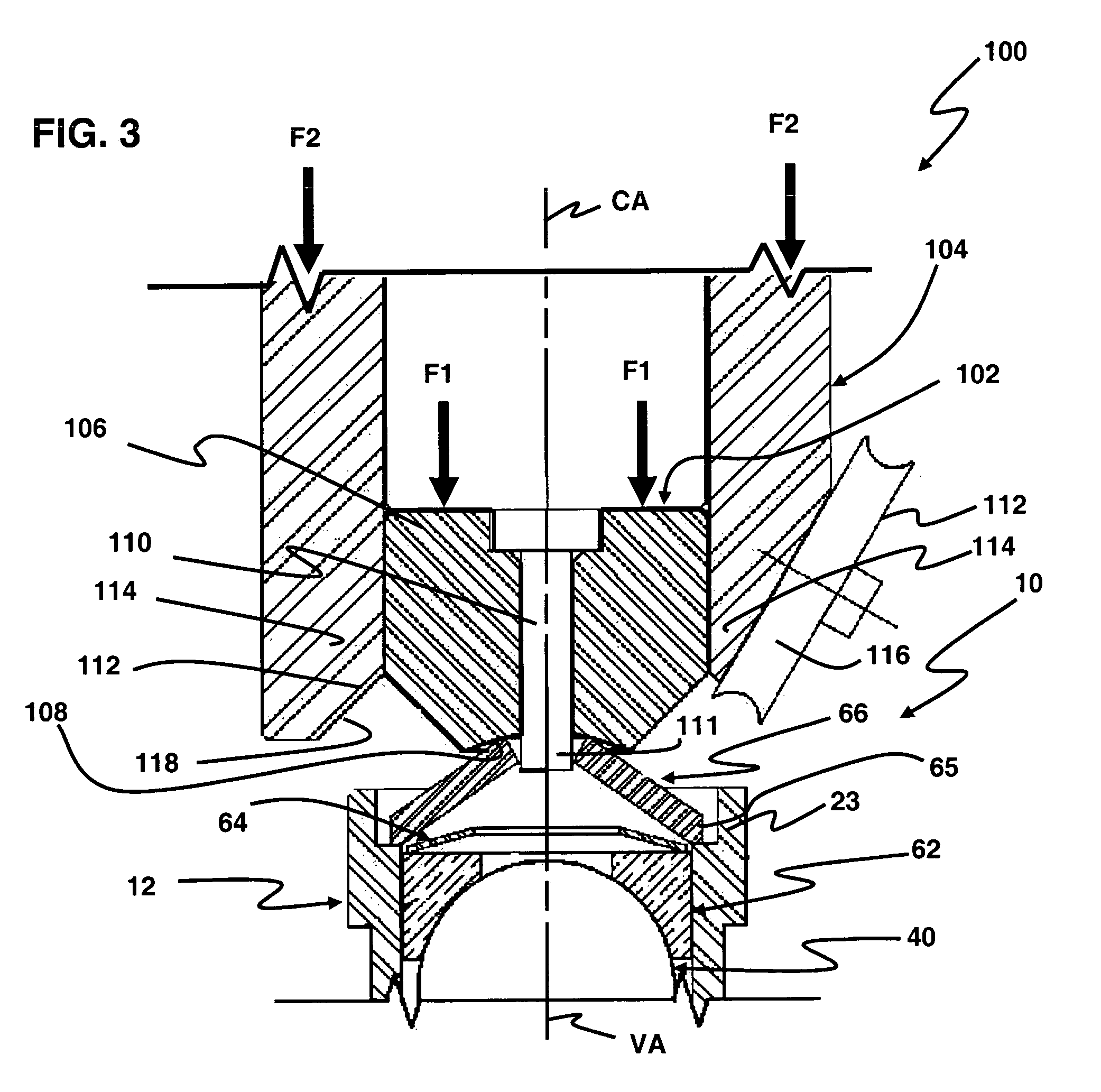
[0035] Turning now to FIGS. 4A-4C, a method of the present invention for assembling a socket includes the initial step of inserting the aforementioned ball and socket components into housing 12 through housing opening 16 to an initial preassembly configuration as shown generally in FIG. 3, or as may be obtained by inserting the components shown in FIG. 1 into housing 12, as described herein. This includes the steps of providing a housing 12 having a central bore 14, the central bore 14 including at least one open end 16 having a counterbore 22 defining a circumferential seat 24 adjacent said open end 16; providing one or more joint components, such as first bearing 30, second bearing 62 and preload device 64, and including stud 36; providing a deformable cover-plate 66, the cover-plate 66 having an outer diameter OD sized to seat within the counterbore 22 on the circumferential seat 24, inserting the stud 36 and joint components into the central bore 14; and placing the cover-plate ...

second embodiment

[0039] Turning now to FIGS. 5A-5C, the method of the present invention for assembling a socket includes the initial step of inserting the aforementioned ball and socket components into housing 12 through housing opening 16 to an initial preassembly configuration as shown generally in FIG. 3, or as may be obtained by inserting the components shown in FIG. 1 into housing 12, as described herein. This includes the steps of providing a housing 12 having a central bore 14, the central bore 14 including at least one open end 16 having a counterbore 22 defining a circumferential seat 24 adjacent said open end 16; providing one or more joint components, such as first bearing 30, second bearing 62 and preload device 64, and including stud 36; providing a deformable cover-plate 66, the cover-plate 66 having an outer diameter OD sized to seat within the counterbore 22 on the circumferential seat 24, inserting the stud 36 and joint components into the central bore 14; and placing the cover-plat...


PUM

PropertyMeasurementUnit
cone angleaaaaaaaaaa

Abstract

A ball and socket housing incorporating a thick housing wall of deformable material adjacent a central bore opening to provide a closure system utilizing a deformable cover-plate. The deformable cover-plate is formed to a desired configuration within the central bore to achieve a consistent internal socket preload. The cover-plate is deformed into the housing opening beyond an elastic limit to control resiliency or spring-back characteristics, thereby achieving a high-degree of repeatability and precise control of the ball and socket preload during the assembly process. The deformed cover-plate is retained in the socket housing at the cover-plate seat by swaged or rolling the perimeter of the housing to capture the perimeter of the deformed cover plate within the housing central bore opening.

Description

CROSS-REFERENCES TO RELATED APPLICATIONS [0001] This patent application claims priority to U.S. Provisional Patent Application Ser. No. 60 / 564,085, filed Apr. 21, 2004, which is hereby incorporated herein by reference in its entirety.BACKGROUND OF THE INVENTION [0002] 1. Technical Field [0003] This invention relates to the manufacturing and assembly of movable sockets, for example, ball-joints as used in automotive steering and suspension systems, and more particularly, to a method and device for performing the operation of closing one end of a movable socket by deforming a solid cover-plate and then spinning or swaging a perimeter lip of the housing to retain the deformed cover-plate. While the invention is described in detail with respect to automotive applications, those skilled in the art will recognize the broader applicability of the invention. [0004] 2. Related Art [0005] Conventional ball-joints, and other movable sockets are used, for example, in automotive steering and sus...

Claims


Application Information

Patent Timeline
Patent Type & Authority Applications(United States)
IPC IPC(8): B21D39/00B21K1/10B21K1/76B21K25/00B23P11/00B23P11/02F16C11/00F16C11/06
CPCB21K25/00B23P11/005B23P2700/11F16C11/0642Y10T29/49853Y10T29/53996Y10T29/49872Y10T403/32737Y10T29/49915Y10T29/4987Y10T403/32631Y10T29/49863Y10T29/49663F16C11/0609F16C11/086
Inventor SPENCE, DALE A.SCHMIDT, GEORGEPARKER, GLEN
Owner FEDERAL MOGUL WORLD WIDE
Learn More