Power tool having noise reducing structure

Inactive Publication Date: 2005-10-27
LEE WEN SUNG
View PDF14 Cites 18 Cited by
  • Summary
  • Abstract
  • Description
  • Claims
  • Application Information

AI Technical Summary

Benefits of technology

[0009] The primary objective of the present invention is to provide a power tool including a structure for reducing shocks and vibrations,

Problems solved by technology

However, the internal gear disk has not been rotatably supported within a housing with any supporting devices or members, such that the internal g

Method used


Image

  • Power tool having noise reducing structure
  • Power tool having noise reducing structure
  • Power tool having noise reducing structure

Examples


Embodiment Construction

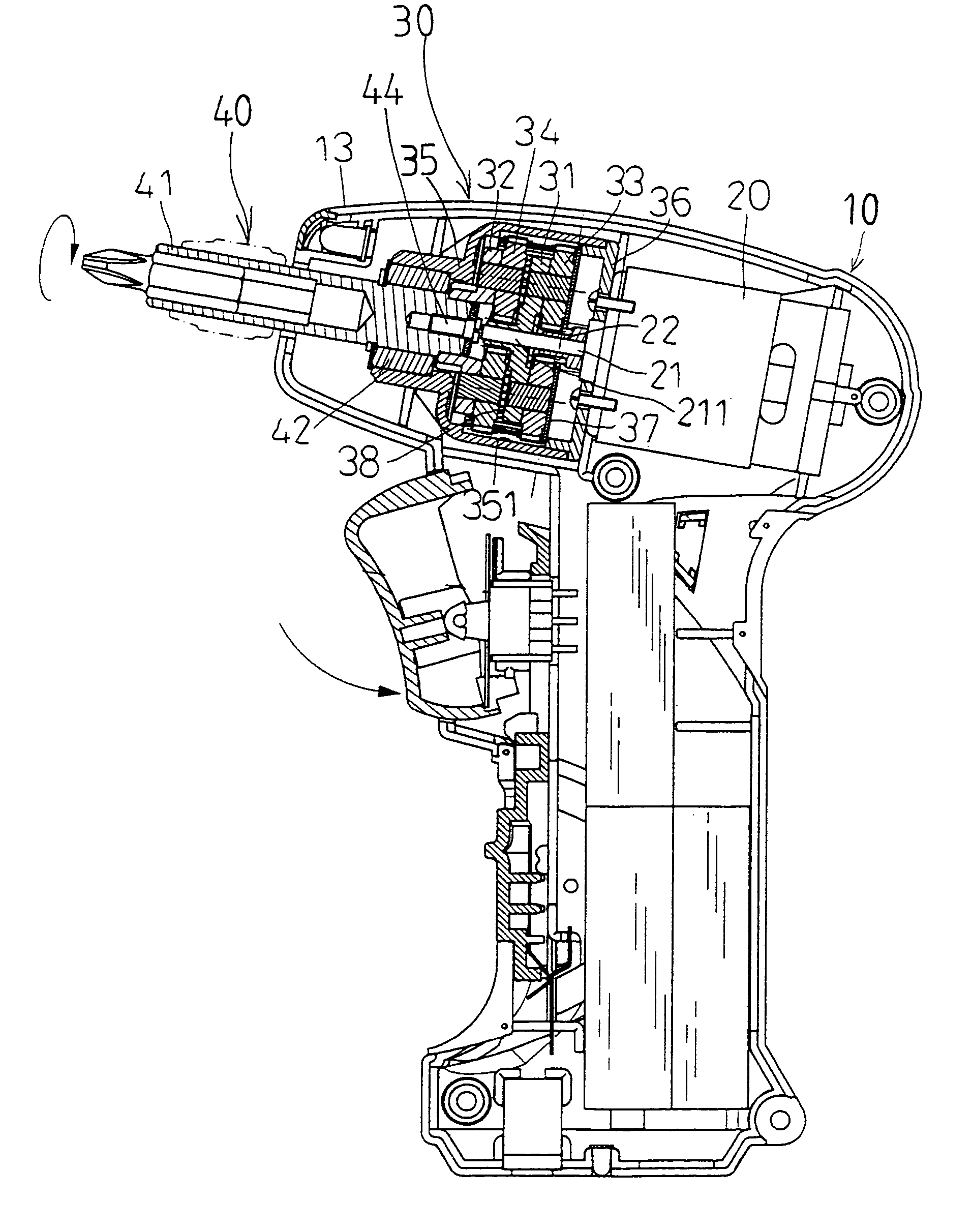
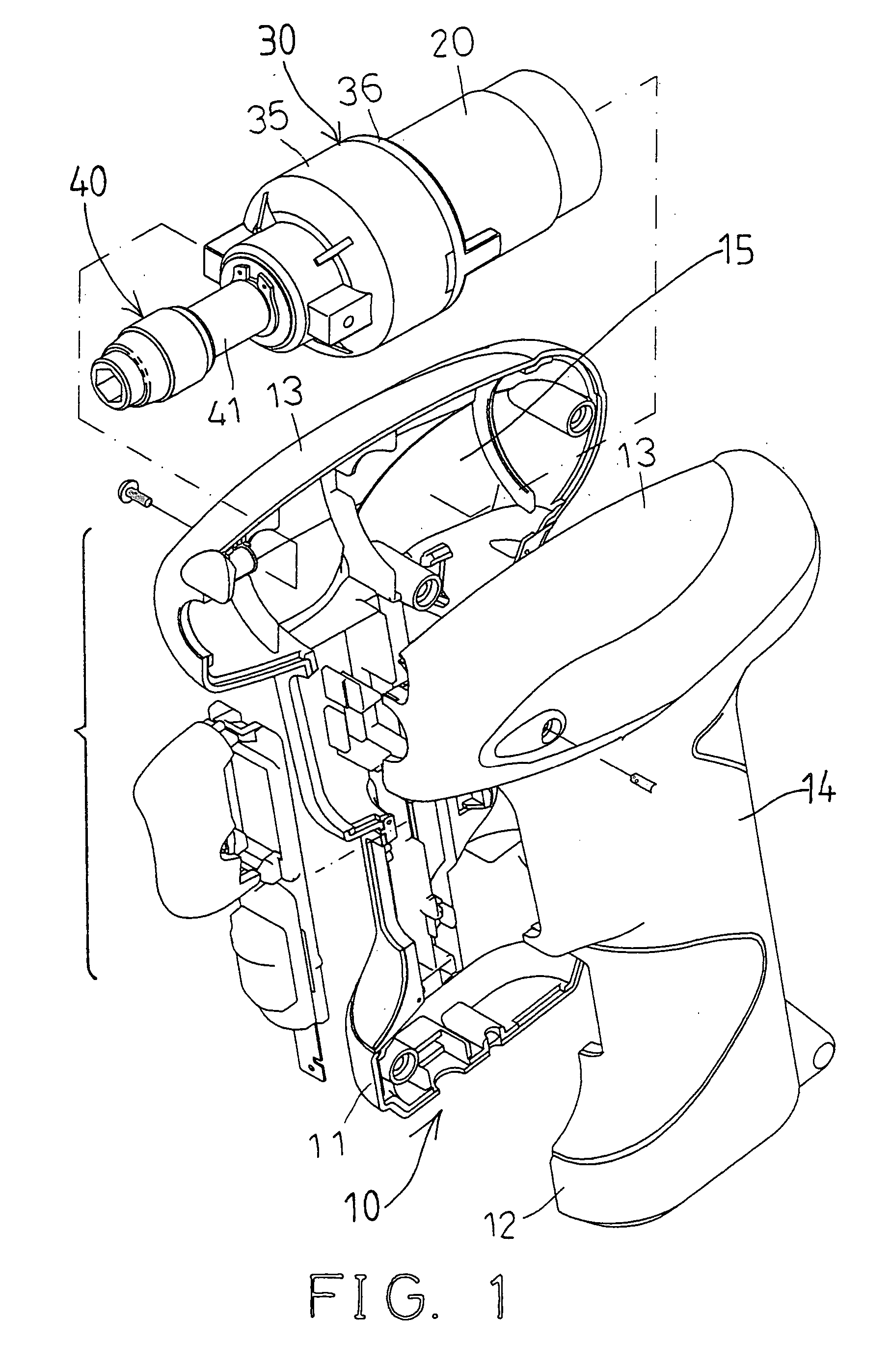
[0022] Referring to the drawings, and initially to FIG. 1, a power tool in accordance with the present invention comprises a body 10 formed and secured by such as two half members 11, 12, and including a container 13 formed or provided on top of a handle 14. The container 13 includes a chamber 15 formed therein for receiving a motor 20 and a reduction gearing 30 therein.

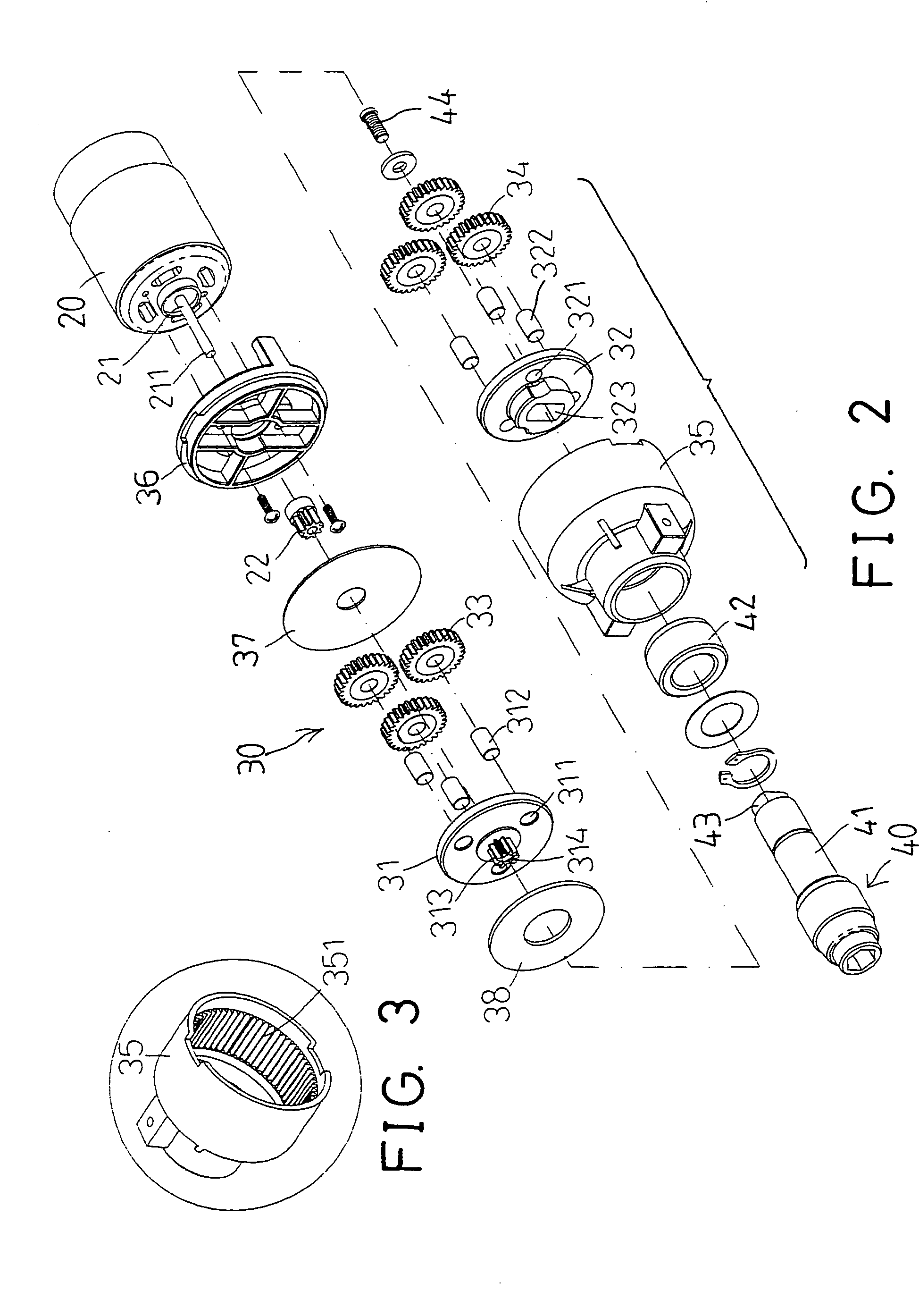
[0023] As shown in FIGS. 2 and 4-5, the motor 20 includes a spindle 21, and a pinion 22 attached or secured onto the spindle 21, so as to be rotated or driven by the motor 20. The spindle 21 of the motor 20 is extended outwardly through or of the pinion 22, and includes a free end 211 extended outwardly beyond the pinion 22, best shown in FIGS. 4 and 6.

[0024] The reduction gearing 30 includes a housing 35 having an internal gear 351 formed or provided therein (FIGS. 3, 5), and a cover 36 attached and secured to the housing 35, for securing the housing 35 to the motor 20. The cover 36 is arranged for allowing the fr...


PUM


Abstract

A power tool includes a container having a chamber to receive a motor which has a spindle attached to a pinion and extended out of the pinion. A reduction gearing includes a housing attached to the motor and having an internal gear, two plates rotatably received in the housing and each having three rotatable gears. The pinion is engaged with the gears of one of the plates which has another pinion engaged with the gears of another plate, to allow the plates and the gears to be rotated by the motor. The pinion of the motor is extended through one of the plates, to smoothly support the plates and the gears within the housing, and to reduce shocks, vibrations, or noises that may be generated by the plates and the gears.

Description

BACKGROUND OF THE INVENTION [0001] 1. Field of the Invention [0002] The present invention relates to a power tool, and more particularly to a power tool having a structure for reducing shocks and vibrations, and thus for reducing noises, and for allowing the power tool to be smoothly driven and operated to effectively rotate or drive fasteners. [0003] 2. Description of the Prior Art [0004] Various kinds of typical power tools have been developed and comprise a reduction gearing coupled to a motor, for being rotated or driven by the motor, to rotate fasteners. [0005] For example, U.S. Pat. No. 6,458,058 to Fu discloses one of the typical power tools comprising a reduction gearing having three or more gears coupled to a pinion of a motor, for being rotated or driven by the motor, to rotate fasteners. Normally, the pinion of the motor is directly engaged within or between the gears, to rotate or drive the gears. [0006] The gears are received in an internal gear disk and engaged with an...

Claims


Application Information

Patent Timeline
IPC IPC(8): B25F5/00E21B3/00
CPCB25F5/006B25F5/001
Inventor LEE, WEN SUNG
Owner LEE WEN SUNG
Why Eureka
Try Eureka